Systems and methods improving optical restoration time in networks

Active Publication Date: 2017-03-23
CIENA
View PDF12 Cites 11 Cited by
  • Summary
  • Abstract
  • Description
  • Claims
  • Application Information

AI Technical Summary

Benefits of technology

[0004]In an exemplary embodiment, a method for improving optical restoration time in a network includes maintaining a status of wavelength load for a plurality of optical links in the network; utilizing the wavelength load to estimate a restoration time for one or more wavelengths being added to each of the plurality of optical links; and determining one or more restoration paths for the one or more wavelengths in the network and considering a total restoration time in selecting a path for each of the one or more wavelengths, wherein each of the one or more restoration paths includes one or more of the plurality of optical links. The maintaining can be performed based on updates from one or more of a control plane and Software Defined Networking (SDN), and wherein the utilizing, and the determining can be performed by one or more of a control plane, a Software Defined Networking (SDN) controller, a Path Computation Element (PCE), a management system, and a planning tool. The estimated restoration time can be a unit of time to add a bundle of wavelengths to a particular optical link, and the estimated restoration time can be derived computationally. Here, the time taken for optically deleting the wavelengths from a faulted link (e.g. following a fiber cut) before adding them to a restoration path are ignored considering the fact that

Problems solved by technology
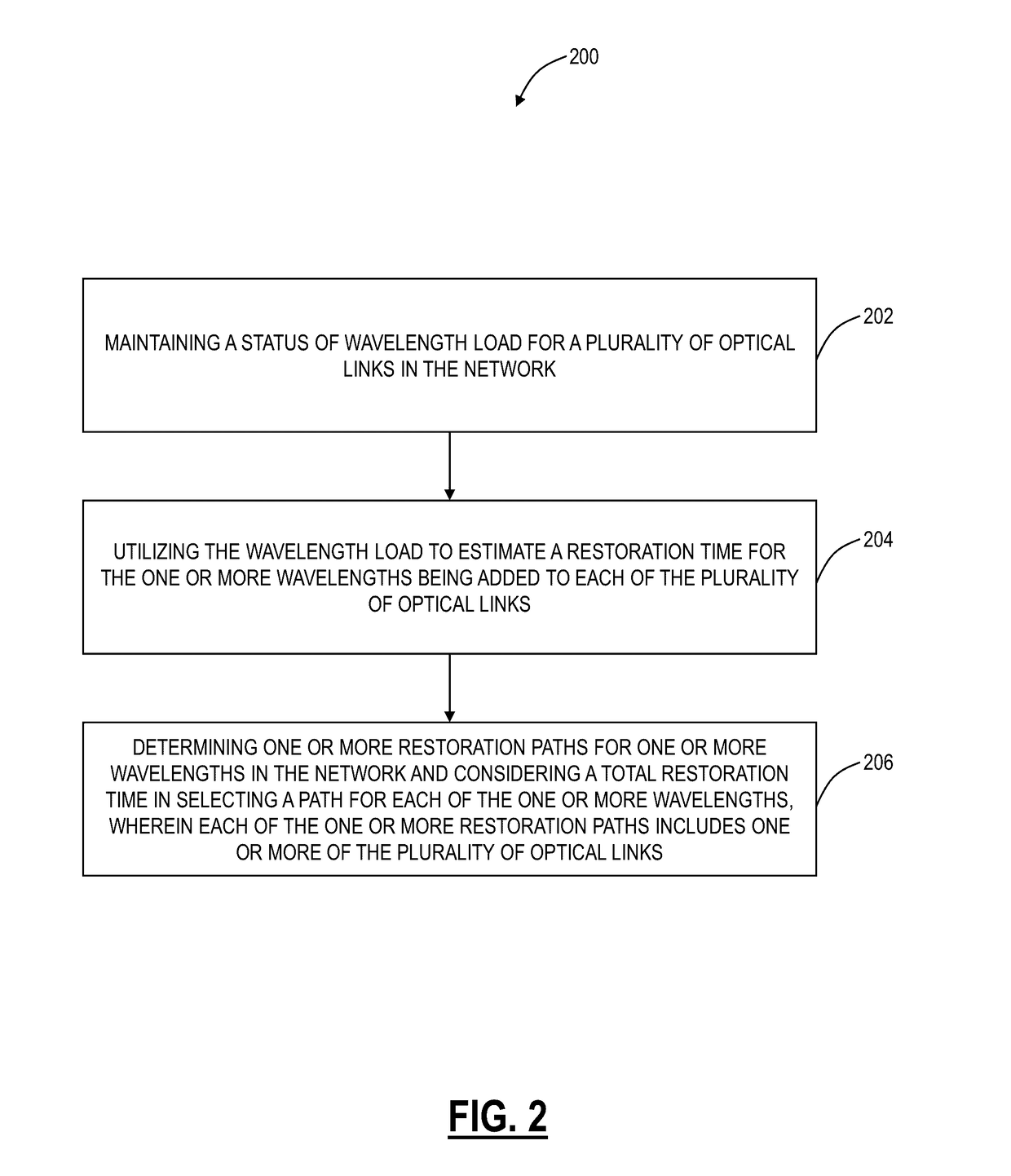
The memory storing instructions that, when executed, can further cause the processor to, subs

Method used


Image

  • Systems and methods improving optical restoration time in networks
  • Systems and methods improving optical restoration time in networks
  • Systems and methods improving optical restoration time in networks

Examples


Embodiment Construction

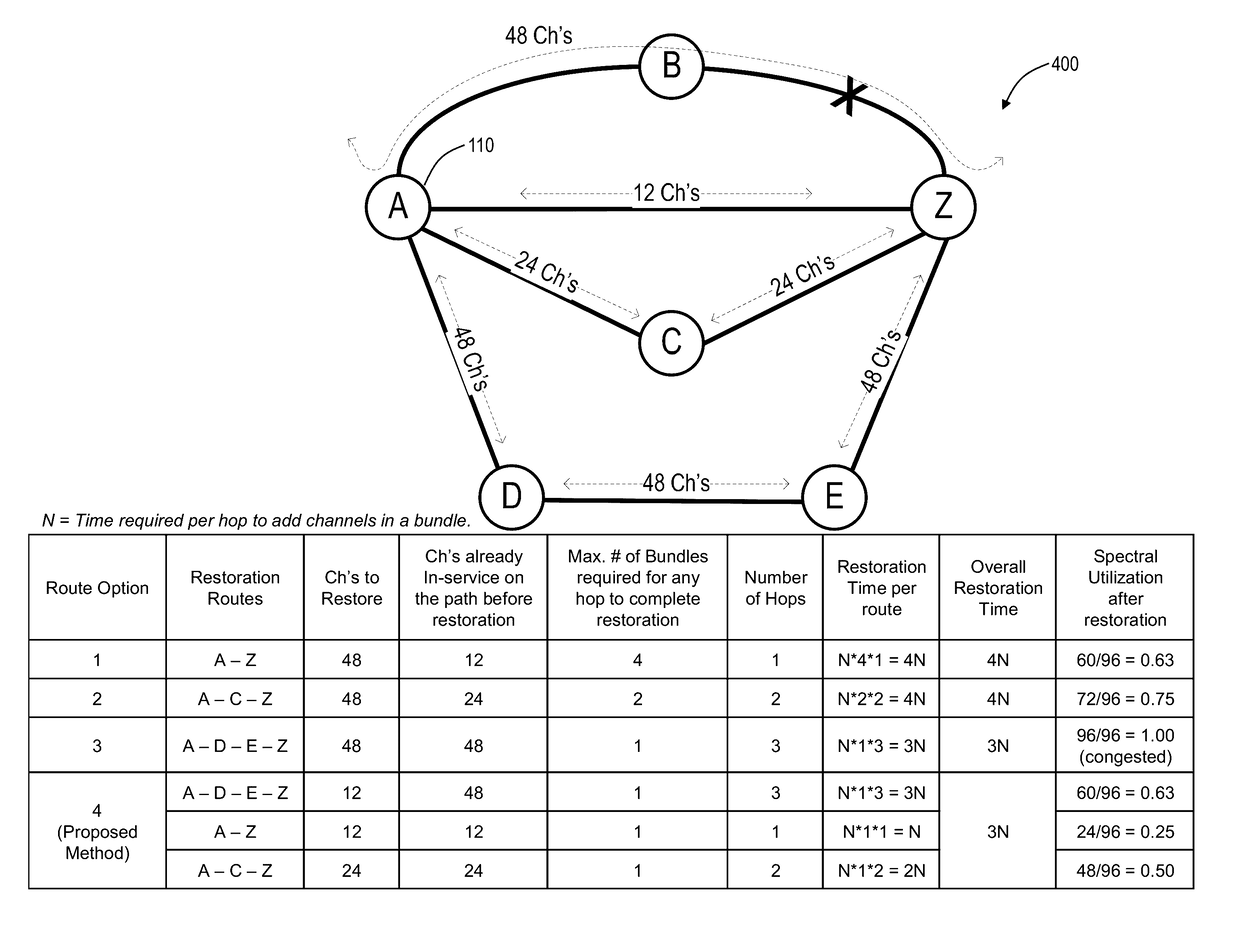
[0014]In various exemplary embodiments, systems and methods are described for improving optical restoration time in networks. The systems and methods augment restoration or path computation techniques by understanding the impact of channel restoration in the presence of existing wavelengths. As such, the systems and methods include computing a network optimal restoration scheme for a given link failure such that all wavelengths are stored in the minimum amount of time. An exemplary objective of the systems and methods is to further take into consideration the number of existing channels on a given link such that the bundles of wavelengths being added to a given link is done in an optimal manner.

Exemplary Network

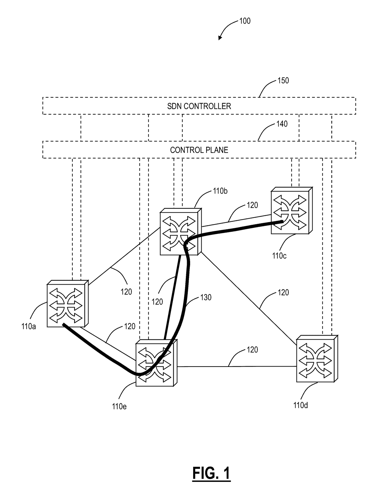
[0015]Referring to FIG. 1, in an exemplary embodiment, a network diagram illustrates an exemplary network 100 with five interconnected nodes 110a, 110b, 110c, 110d, 110e. The nodes 110 are interconnected through a plurality of links 120. The nodes 110 communicate with one ano...


PUM


Abstract

Systems and methods for improving optical restoration time in a network include maintaining a status of wavelength load for a plurality of optical links in the network; utilizing the wavelength load to estimate a restoration time for one or more wavelengths being added to each of the plurality of optical links; and determining one or more restoration paths for the one or more wavelengths in the network and considering a total service restoration time in selecting a path for each of the one or more wavelengths, wherein each of the one or more restoration paths comprises one or more of the plurality of optical links.

Description

FIELD OF THE DISCLOSURE[0001]The present disclosure generally relates to optical network systems and methods. More particularly, the present disclosure relates to systems and methods improving optical restoration time in networks.BACKGROUND OF THE DISCLOSURE[0002]Optical networks and the like (e.g., Dense Wave Division Multiplexing (DWDM), Optical Transport Network (OTN), Ethernet, and the like) at various layers are using distributed control planes and / or centralized controlled via Software Defined Networking (SDN). Control planes provide an automatic allocation of network resources in an end-to-end manner. Exemplary control planes may include Automatically Switched Optical Network (ASON) as defined in ITU-T G.8080 / Y.1304, Architecture for the automatically switched optical network (ASON) (February 2005), the contents of which are herein incorporated by reference; Generalized Multi-Protocol Label Switching (GMPLS) Architecture as defined in IETF Request for Comments (RFC): 3945 (Oc...

Claims


Application Information

Patent Timeline
IPC IPC(8): H04B10/03H04J14/02
CPCH04J14/0201H04B10/03H04J14/0268
Inventor AL SAYEED, CHOUDHURY A.SWINKELS, GERARD LEO
Owner CIENA
Why Eureka
Try Eureka