
Emergency power supply circuit for dimmable electronic ballasts and related method

a technology of electronic ballast and power supply circuit, which is applied in emergency power supply arrangements, instruments, process and machine control, etc., can solve the problems of increased field claims, non-uniform distribution of current between the lamps in dimmed operation, and inability to provide dimmed operation. to achieve the effect of efficient operation managemen

Inactive Publication Date: 2011-07-28
OSRAM GMBH
View PDF9 Cites 24 Cited by
  • Summary
  • Abstract
  • Description
  • Claims
  • Application Information

AI Technical Summary

Benefits of technology

[0011]avoid additional cabling to the lamp or lamps, thus dispensing with undesirable effects on the distribution of the current over various lamps in a multi-lamp light source,
[0013]provide for more efficient managing of operation in emergency conditions.
[0021]In an embodiment, a low frequency AC ripple is added to the DC output to improve EMC (Electro-Magnetic Compatibility) behaviour.

Problems solved by technology

Such an approach works quite well for non-dimmable ballasts but exhibits drawbacks during normal operation of dimmable ballasts and may be the source of complaints and requests for assistance in-the-field.
For example, such arrangements may result in an additional asymmetric capacitive load for a dimmable electronic ballast, which may lead to a non-uniform distribution of currents between the lamps in dimmed operation.
Also, wiring errors occur quite often leading to increased field claims.
For example, document DE 202 19 737 U1 discloses such an emergency power supply circuit, which however does not provide for dimmed operation.

Method used


Image

  • Emergency power supply circuit for dimmable electronic ballasts and related method
  • Emergency power supply circuit for dimmable electronic ballasts and related method
  • Emergency power supply circuit for dimmable electronic ballasts and related method

Examples


Embodiment Construction

[0025]In the following description, numerous specific details are given to provide a thorough understanding of embodiments. The embodiments can be practiced without one or more of the specific details, or with other methods, components, materials, etc. In other instances, well-known structures, materials, or operations are not shown or described in detail to avoid obscuring aspects of the embodiments.

[0026]Reference throughout this specification to “one embodiment” or “an embodiment” means that a particular feature, structure, or characteristic described in connection with the embodiment is included in at least one embodiment. Thus, the appearances of the phrases “in one embodiment” or “in an embodiment” in various places throughout this specification are not necessarily all referring to the same embodiment. Furthermore, the particular features, structures, or characteristics may be combined in any suitable manner in one or more embodiments.

[0027]The headings provided herein are for...


PUM


Abstract

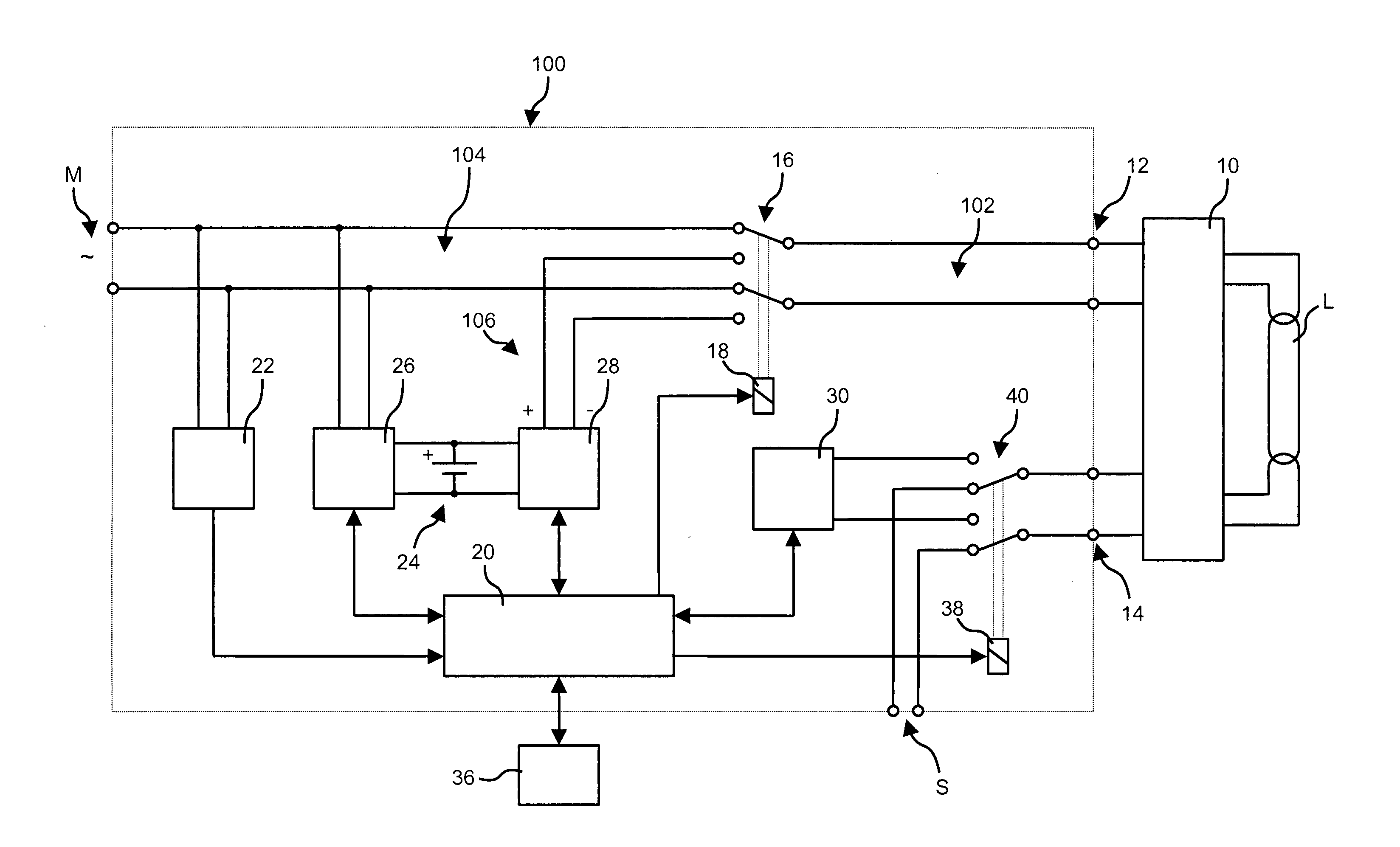
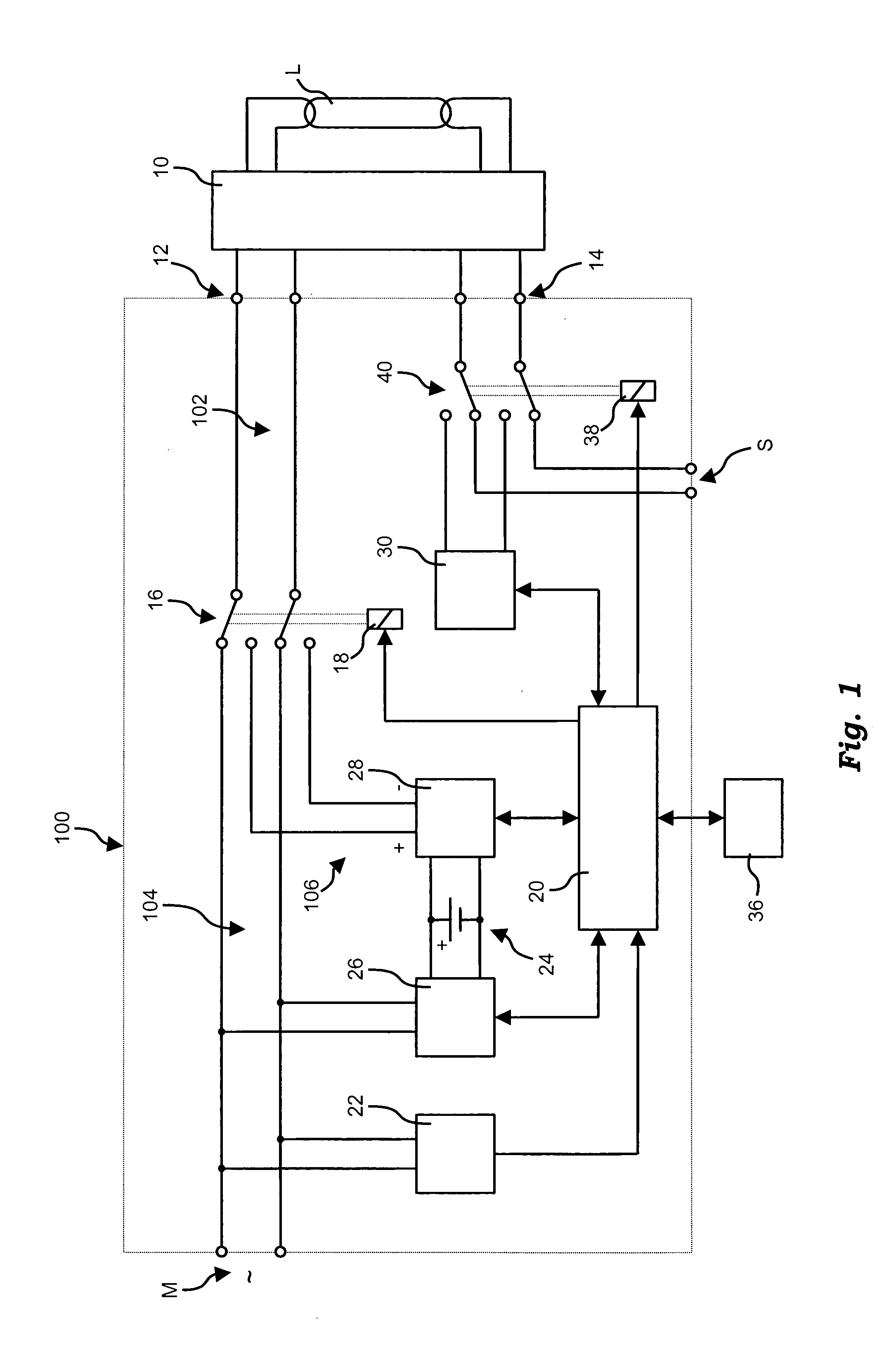
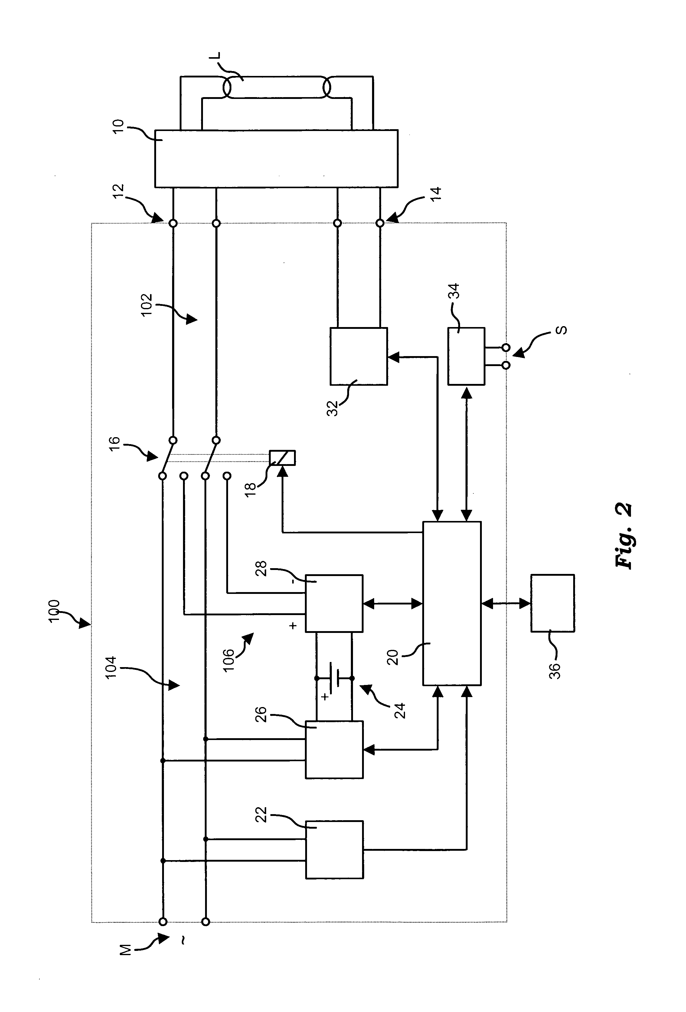
An emergency supply circuit for an electronic ballast may include: an output line to feed a supply input of the ballast; a first line to receive a mains supply signal; a second line to receive an emergency supply signal from a battery, with a converter interposed in said second line to boost said supply signal, a switch to alternatively connect said output line to said first or said second line; a controller sensitive to the absence of said mains supply signal and to the charge level of said battery, said controller to produce switching of said switch to connect said output line to said second line in the absence of said mains supply signal on said first line, whereby said output line receives said supply signal, and dimming interface circuitry to drive said dimming control input of said ballast when said output line is connected to said second feed line.

Description

FIELD OF THE INVENTION[0001]This disclosure relates to emergency power supply circuits.[0002]More specifically, this disclosure relates to emergency power supply circuits for dimmable electronic ballasts feeding e.g. light sources.DESCRIPTION OF THE RELATED ART[0003]Certain existing emergency ballasts, e.g. for driving multiple lamps, provide for the electronic ballast to be disconnected from the mains in the case of a mains failure. One of the lamps driven by the electronic ballast is disconnected (e.g. via a relay) from the electronic ballast and coupled to a high-frequency supply source of an emergency ballast. Typically, the lamp is driven in a dimmed condition for reducing power consumption, and the emergency supply continues until the mains feed is re-established or the battery of the emergency ballast is exhausted.[0004]Such an approach works quite well for non-dimmable ballasts but exhibits drawbacks during normal operation of dimmable ballasts and may be the source of compl...

Claims


Application Information

Patent Timeline
IPC IPC(8): H05B37/02
CPCH02J9/065H02J9/06H05B41/38
Inventor LIESS, UWE
Owner OSRAM GMBH
Learn More