Self-loading Firearm

Inactive Publication Date: 2011-08-04
ZIMMERMAN JEREMY
View PDF7 Cites 6 Cited by
  • Summary
  • Abstract
  • Description
  • Claims
  • Application Information

AI Technical Summary

Benefits of technology

[0006]In a first, separate aspect the present invention is a self-loading firearm that includes a unitary portion including a human interface and a barrel defining a longitudinal dimension. A slidable portion is attached to the unitary portion so as to permit the slidable portion to slide in the longitudinal dimension. The slidable portion includes at least a portion of a firing chamber. In addition, a lock is adapted to selectably fix the slidable portion relative

Problems solved by technology

The unlocking of the two portions, however, cannot take place too quickly after firing the cartridge, because immediately after firing the barrel contains highly pressurized gas that would be dangerous if released prematurely.
Unfortunately, the mechanisms currently employed to use the recoil of the firearm in locked breech pistols all suffer from one or both of two drawbacks.
First, for currently available mechanisms, the delay is inversely proportional to the intensity of the ordinance used.
Accordingly, the need for a sufficient unlocking delay places an upper limit on ordinance intensity.
S

Method used


Image

  • Self-loading Firearm
  • Self-loading Firearm
  • Self-loading Firearm

Examples


Embodiment Construction

)

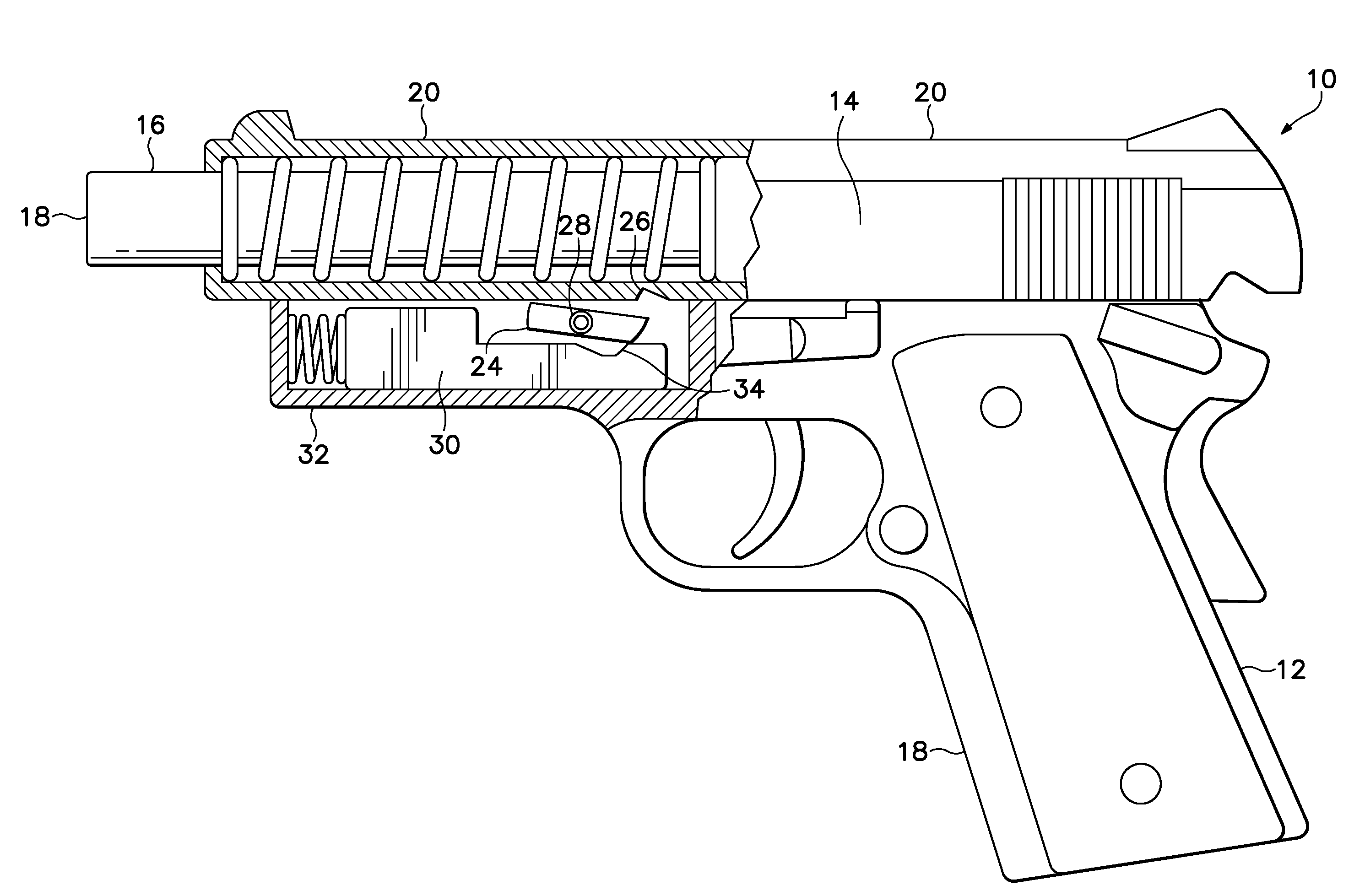
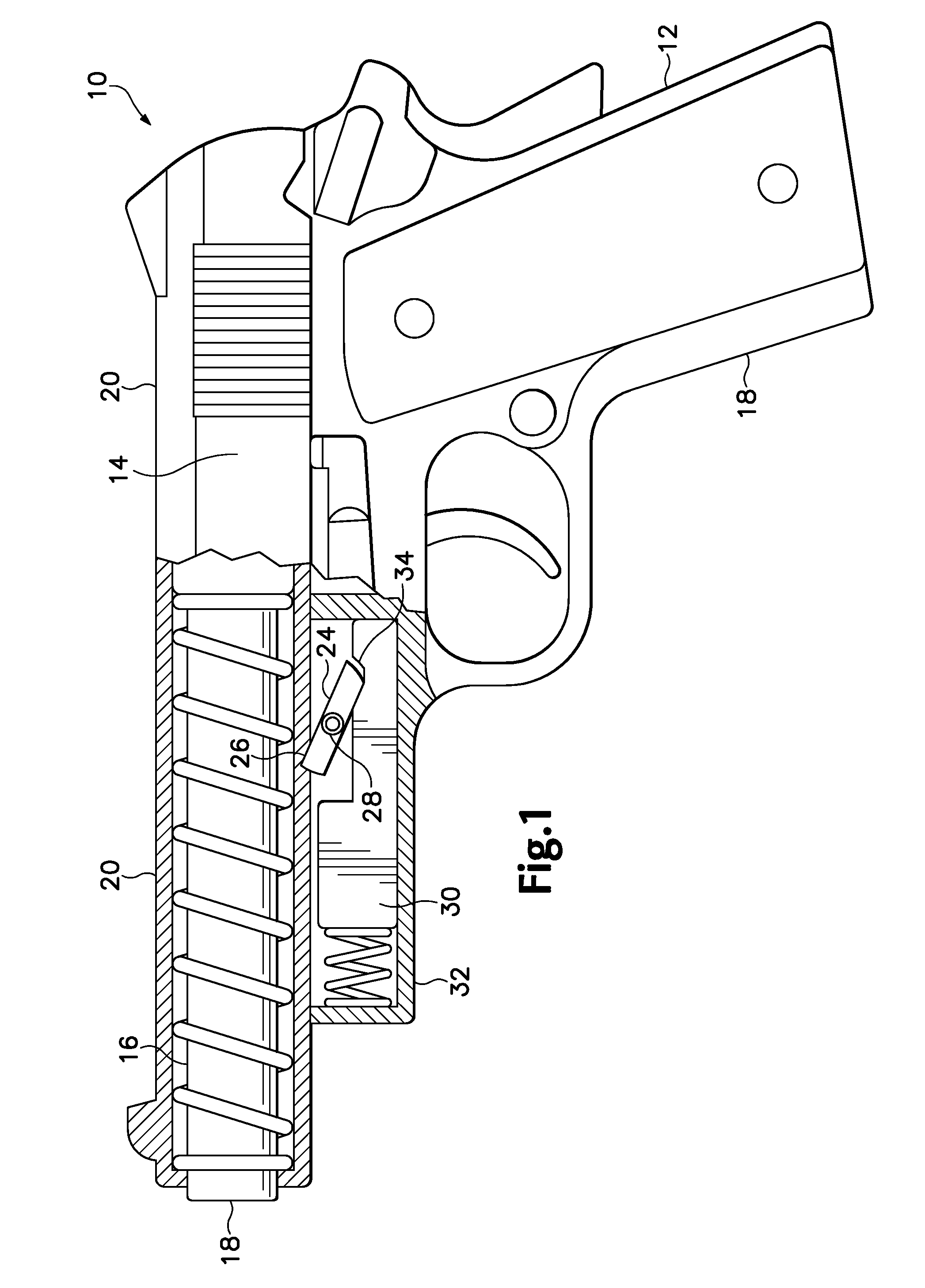
[0012]Referring to FIG. 1, a firearm 10 constructed according to the present invention includes a handgrip 12, a firing chamber 14, and a barrel 16. The handgrip 12 and barrel 16 form a portion of a first part 18, which engages with a second part 20 that is in the form of a slider. Second part 20 includes the breech block face and is generally locked to the first part18, but is briefly unlocked and permitted to translate relative to first part 18, shortly after firearm 10 is fired, as will be described below.

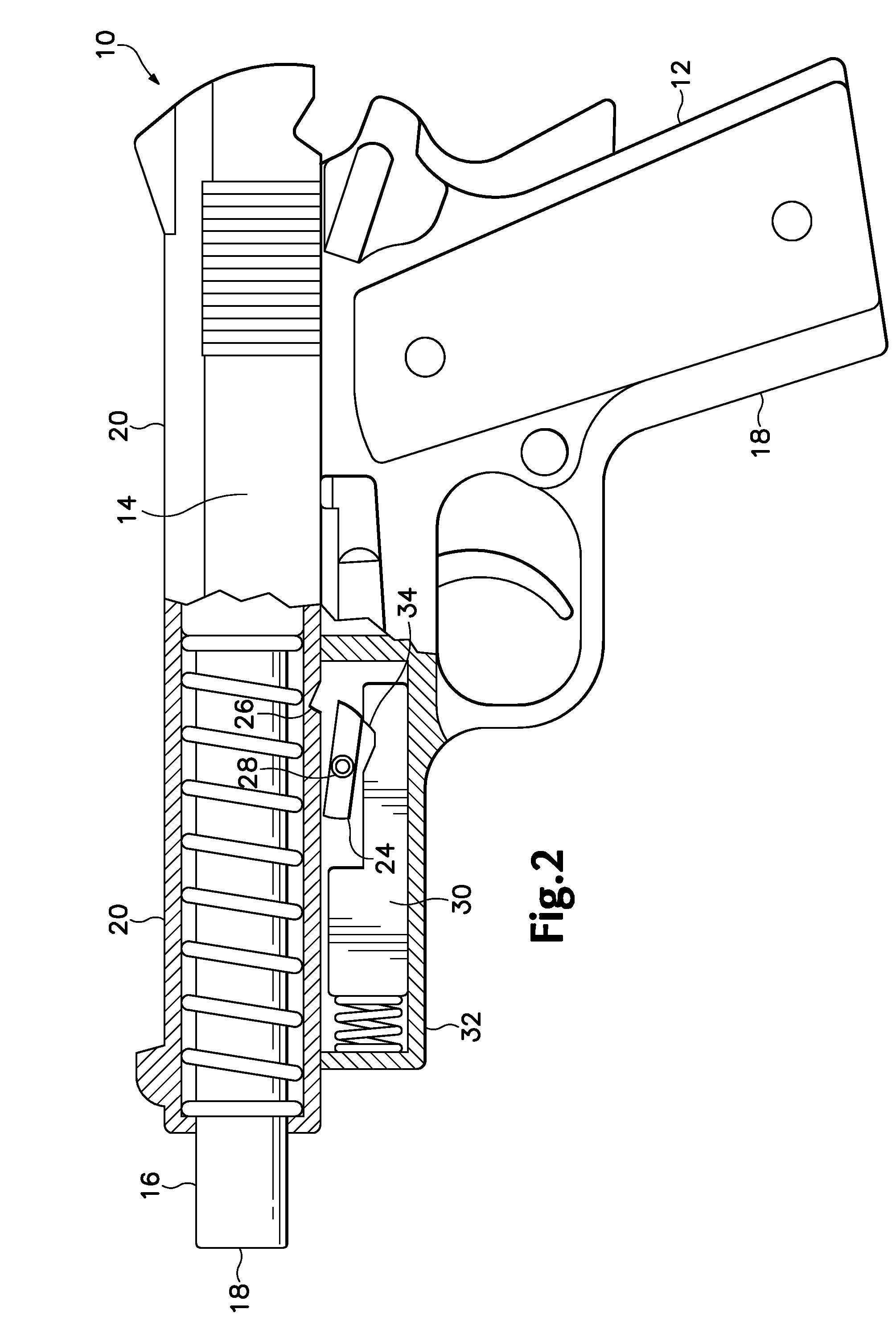
[0013]To maintain first part 18 and second part 20 in locked relationship, a locking piece 24 is mounted on first part 18 and urged into locking contact with a notch 26 defined in second part 20, by a spring 28, mounted in first part 18. Referring also to FIG. 2, when the firearm 10 is fired, an inertial piece 30 that is retained by a recess wall 32, retains its position as the remainder of firearm 10 is accelerated in a rearward direction. Locking piece 24 and inertial piece 3...


PUM


Abstract

An automatic firearm that includes a unitary portion including a human interface and a barrel defining a longitudinal dimension. A slidable portion is attached to the unitary portion so as to permit the slidable portion to slide in the longitudinal dimension. The slidable portion includes at least a portion of a firing chamber. In addition, a lock is adapted to selectably fix the slidable portion relative to the unitary portion. Also, a chamber attached to the unitary portion and an inertial member permitted to move inside the chamber and urged into a first position, the inertial member adapted to translate into a second position, displaced from said first position by at least 0.1 cm, upon firing of the firearm, in which second position the inertial member begins to change the position of the lock, thereby permitting the moveable portion to move relative to the unitary portion.

Description

RELATED APPLICATION[0001]This application is a continuation-in-part of application Ser. No. 11 / 093,715, filed Mar. 29, 2005, which is hereby incorporated by reference as if fully set forth herein.BACKGROUND OF THE INVENTION[0002]In a recoil operated self-loading firearm the “recoil” motion caused by firing is harnessed to unlock a portion that moves relative to the handgrip (in the case of a hand gun) or buttstock (in the case of a rifle). This relative motion is used to eject the spent cartridge case and to load another cartridge into the firing chamber, from a stock of cartridges held in a magazine.[0003]The unlocking of the two portions, however, cannot take place too quickly after firing the cartridge, because immediately after firing the barrel contains highly pressurized gas that would be dangerous if released prematurely. Too overcome this problem many mechanisms have been invented for unlocking the two firearm sections, after a short delay, to permit the bullet to leave the ...

Claims


Application Information

Patent Timeline
IPC IPC(8): F41A3/00F41C3/00F41C7/00
CPCF41A3/00F41C7/00F41C3/00F41A5/02F41A17/00
Inventor ZIMMERMAN, DAVID A.
Owner ZIMMERMAN JEREMY
Why Eureka
Try Eureka