System and method for generating automatic user interface for arbitrarily complex or large databases

a database and user interface technology, applied in relational databases, web data retrieval, instruments, etc., can solve the problems of unfavorable use, unfavorable user experience, and high complexity of manual coding, and achieve the effect of natural, powerful, and easy-to-us

Inactive Publication Date: 2011-08-04
KAUFMAN MICHAEL PHILIP
View PDF37 Cites 131 Cited by
  • Summary
  • Abstract
  • Description
  • Claims
  • Application Information

AI Technical Summary

Benefits of technology

[0013]It is yet a further object of the invention that the application so presented reveals (and enforces) the relational / hierarchical organization among the tables within the back-end via smoothly integrated UI mechanisms which are embedded directly into the base-table screen displays—providing a natural, powerful, and easy-to-use environment for managing complex data relationships and interactions.
[0014]One embodiment (the “reference implementation”) of the present invention achieves these and other objects by providing a system, currently written in Java and JSP, which automatically and dynamically (“on-the-fly”) generates (in HTML, Javascript, and HTTP / CGI code), a fully functional system, based upon, and connected directly to, the underlying data model (as instantiated within an Oracle8i SQL RDBMS). The UI is built based on an automated interrogation of the RDBMS, either as needed (on-the-fly) or by building an in-memory representation of the data model. The generated UI comprises all mode displays (e.g., browse, search, edit, and add) for all tables, and a full complement of mechanisms, integrated into the mode displays for representing, navigating, and managing relationships across tables. This embodiment has the capability of creating such a UI where the underlying RDBMS is complex and comprises a plurality of tables, constraints, and relationships. It utilizes a hierarchical “context stack” for maintaining (and suspending) the working state of a particular table (comprising selected record, display “mode”, pending form-field entries, in-effect search-filter parameters, Browse-mode scroll position, and any filter constraints imposed from above stack contexts) while “drilling down” across relationships to work with related information (in a possibly constrained working context) and returning relevant changes to the parent-context table, and a corresponding UI convention for displaying and navigating this stack. The embodiment provides a set of rules for traversing / navigating the context stack. It further provides naming conventions and annotational methods for enhancing and extending the representation of table structures, constraints, and relationships within the back-end so as to more fully support revelation of the schema structure through external interrogation.

Problems solved by technology

Moreover, the construction of front-end applications is generally undertaken using conventional third- or fourth-generation computer languages, which require by-hand coding at a very low level of functionality.
Even with such tools, considerable work remains in building a complete, fully functional VI for a back-end schema of any appreciable size or complexity—especially where industrial-grade performance and reliability is required.
And as enterprise-scale data models continue to grow, the attendant explosion of manual-coding requirements quickly becomes unwieldy—and eventually, untenable.

Method used


Image

  • System and method for generating automatic user interface for arbitrarily complex or large databases
  • System and method for generating automatic user interface for arbitrarily complex or large databases
  • System and method for generating automatic user interface for arbitrarily complex or large databases

Examples


Embodiment Construction

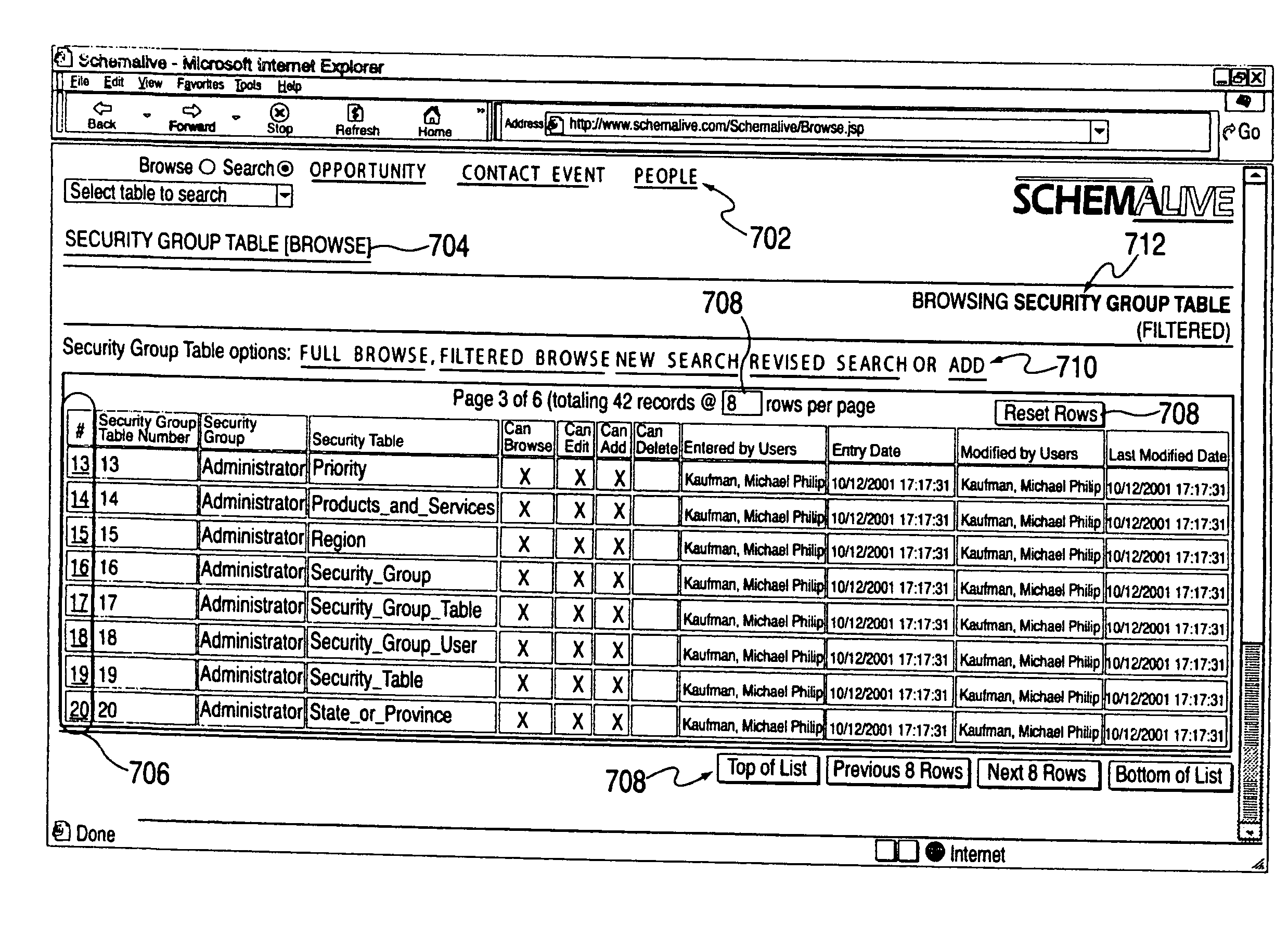
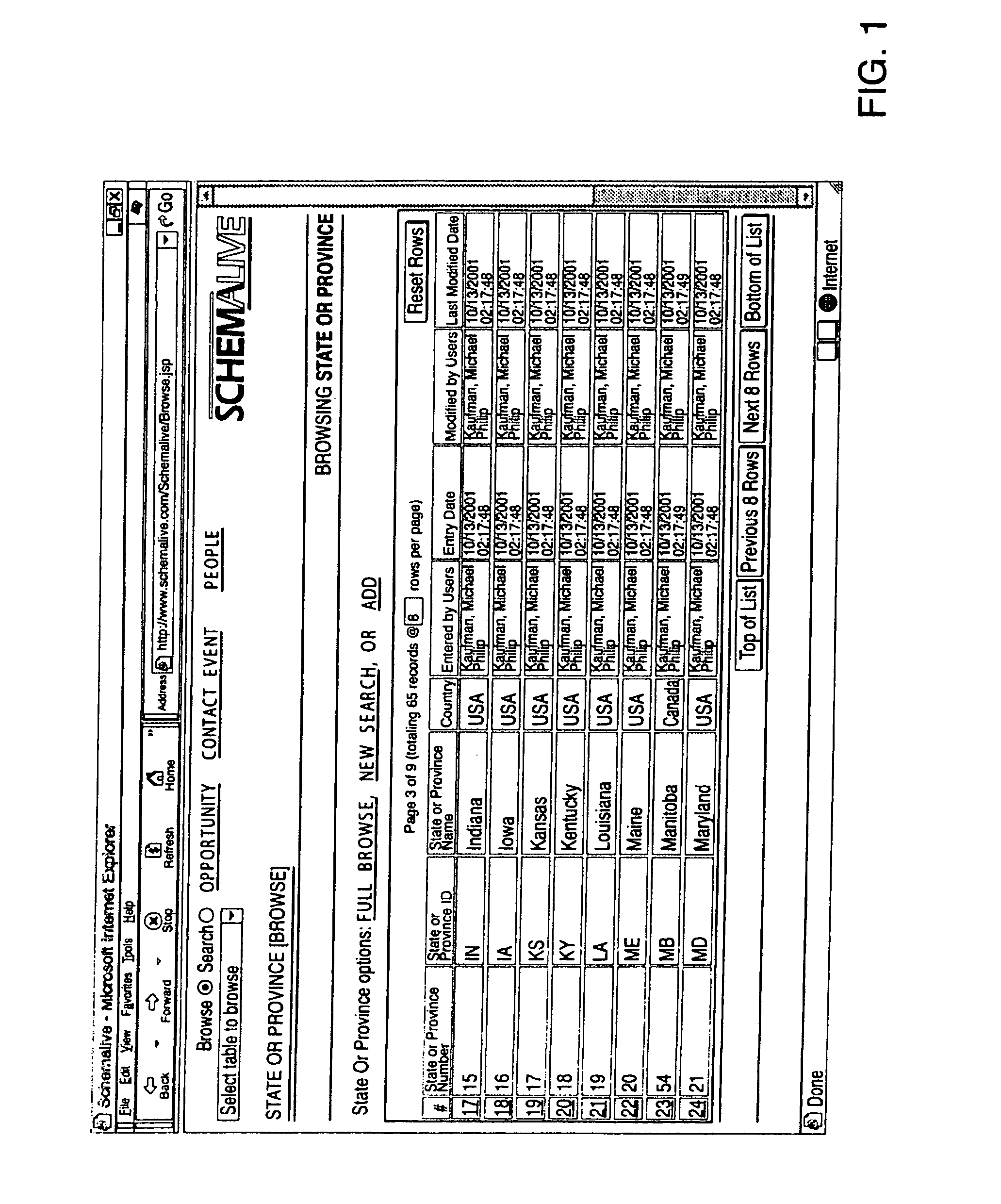
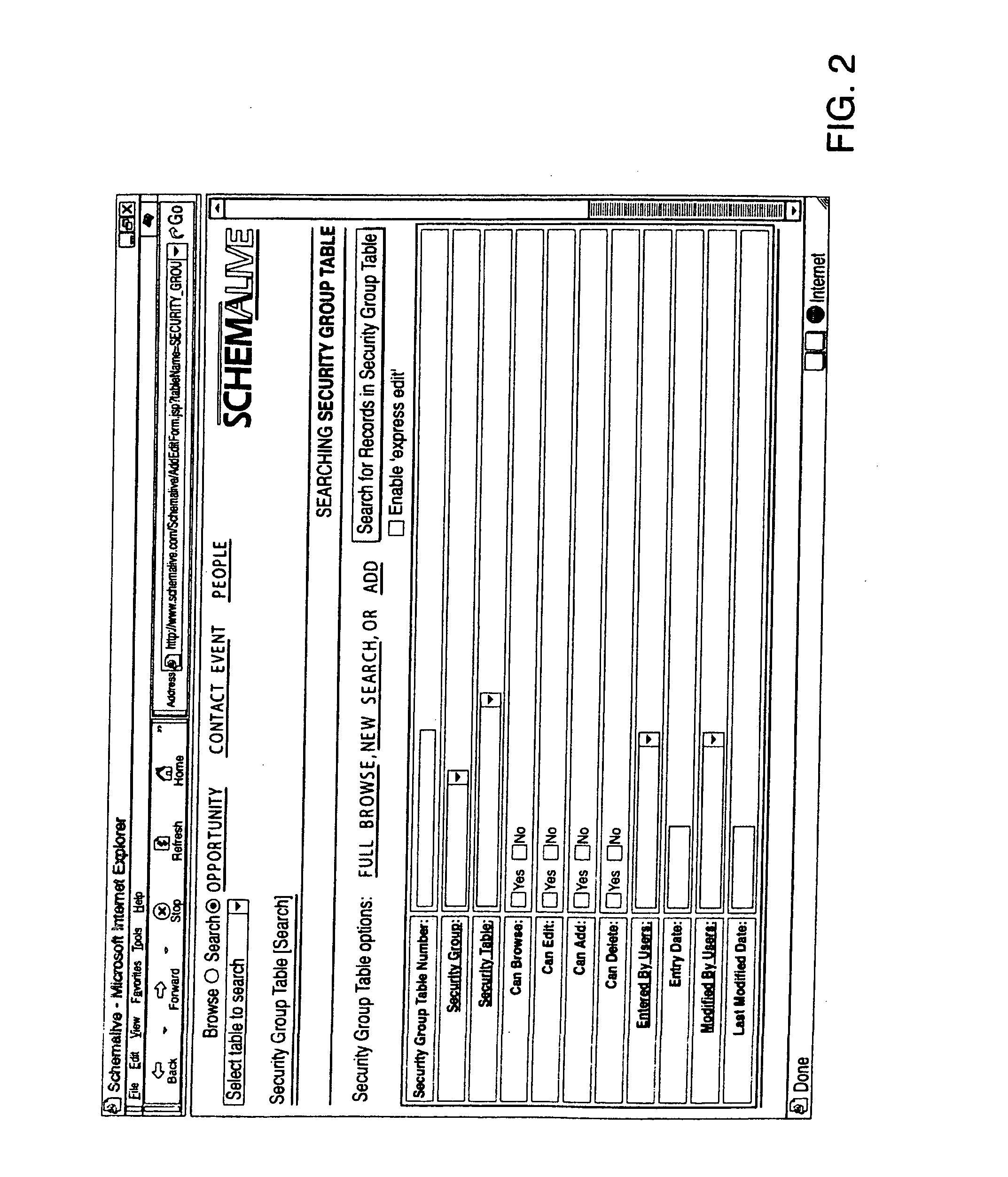
[0026]The preferred embodiment of the invention, as illustrated in FIGS. 1 through 9E, corresponds in most respects to an implementation of the invention being developed under the trademark SCHEMALIVE™ which is herein referred to as the “reference implementation,” The preferred embodiment is further represented substantially in full by the reference-implementation source code files, documentation and scripts in the appendices accompanying and incorporated by reference into this application, as further described in the text that follows. The preferred embodiment includes in addition some further developments which are herein described which have not as yet been rendered in the reference implementation.

[0027]Although the invention has been most specifically illustrated with a particular preferred embodiment, it should be understood that the invention concerns the principles by which such embodiment may be designed, and is by no means limited to the configuration shown.

[0028]As can be ...


PUM


Abstract

A software system automatically and dynamically generates a fully functional user interface (UI) based upon, and connected directly to, an underlying data model (as instantiated within a relational database management system (RDBMS)). The UI derives from an automated interrogation of the RDBMS, and comprises all mode displays (e.g., browse, search, edit, add) for all tables, and a full complement of mechanisms—integrated directly into the mode displays—for representing, navigating, and managing relationships across tables, regardless of the complexity of the underlying RDBMS schema. It utilizes a hierarchical “context stack” for suspending the working state of a particular table while “drilling down” to work with related-table information and return relevant changes to the base table. The embodiment further provides methods to enhance and extend the internal representation of table structures, constraints, relationships, and—special requirements (“business rules”) for improved revelation of the schema structure through external interrogation.

Description

CROSS-REFERENCE TO RELATED APPLICATIONS[0001]This application is a divisional of U.S. patent application Ser. No. 11 / 925,236, filed Oct. 26, 2007, which is a continuation of U.S. patent application Ser. No. 10 / 428,209, filed Apr. 30, 2003, now issued as U.S. Pat. No. 7,318,066, which is a continuation of International Application No. PCT / US01 / 42867, filed Oct. 31, 2001, which claims priority to U.S. patent application Ser. No. 09 / 703,267, filed Oct. 31, 2000, now abandoned, and U.S. Provisional Patent Application Ser. No. 60 / 276,385, filed Mar. 16, 2001.COMPUTER PROGRAM LISTING[0002]The computer program listing submitted on compact disc is hereby incorporated by reference. The compact disc contains the following directory structure:File Name and PathDate of CreationSize in BytesSchemalive / AddEditForm.jsp10 / 30 / 200136,431Schemalive / BalloonHelp.jsp10 / 30 / 20012,375Schemalive / Browse.jsp10 / 30 / 200142,376Schemalive / DataDictionary.jsp10 / 30 / 20011,501Schemalive / DoAddEdit.jsp10 / 30 / 200118,925Sche...

Claims


Application Information

Patent Timeline
Patent Type & Authority Applications(United States)
IPC IPC(8): G06F7/00
CPCG06F17/30286G06F17/30864G06F7/00G06F17/30289G06F3/0481G06F3/0484Y10S707/912G06F16/21G06F16/20G06F16/951G06F16/284
Inventor KAUFMAN, MICHAEL PHILIPSILVERMAN, MICAH PHILIP
Owner KAUFMAN MICHAEL PHILIP
Why Eureka
Try Eureka