
Sliding input user interface

Inactive Publication Date: 2011-08-04
NOKIA CORP
View PDF6 Cites 132 Cited by
  • Summary
  • Abstract
  • Description
  • Claims
  • Application Information

AI Technical Summary

Benefits of technology

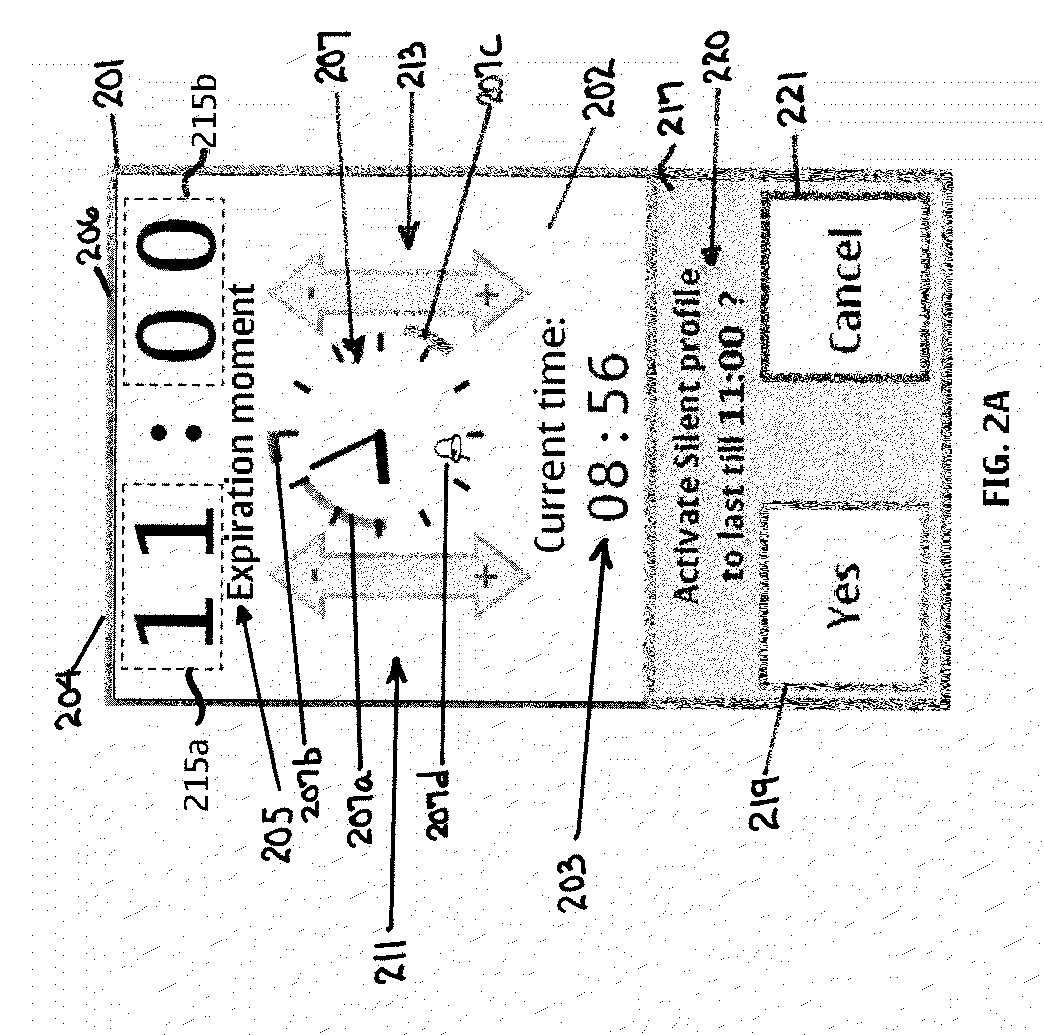
[0009]In one aspect a method includes using a device to detect a signal corresponding to a sliding input on a touch sensitive area of the device, the sliding input being for a time setting adjustment. A time unit corresponding to a start point of the sliding input is determined, and if the signal indicates that the sliding input is substantially in a first direction, a time setting of the corresponding time unit is increased by a pre-defined increment, and if the signal indicates that the sliding input is substantially in a second direction, the time setting of the corresponding time unit is decreased by a pre-defined increment. Feedback signals are provided at regular intervals of length, along or corresponding to the route of the sliding movement. Those feedback signals can be sensed or felt, which helps in using the device without looking at the screen. This enables the eyes-free-operation of the device for most time settings, so that they can be made with a single hand, for example with the thumb of the hand which holds the device.

Problems solved by technology

However, there are situations when the user may not wish to have audible or otherwise normal alerts.
In mobile phones that use for example the “S60™ 5th edition” user interface of Nokia™, to set an expiration moment for a timed mode or profile, the buttons or keys (which can include menu setting selections) must be pressed or activated anywhere between 12-19 times. In some situations, adjusting these settings can take more time than the user has available, or can be overly distracting.

Method used


Image

  • Sliding input user interface
  • Sliding input user interface
  • Sliding input user interface

Examples


Embodiment Construction

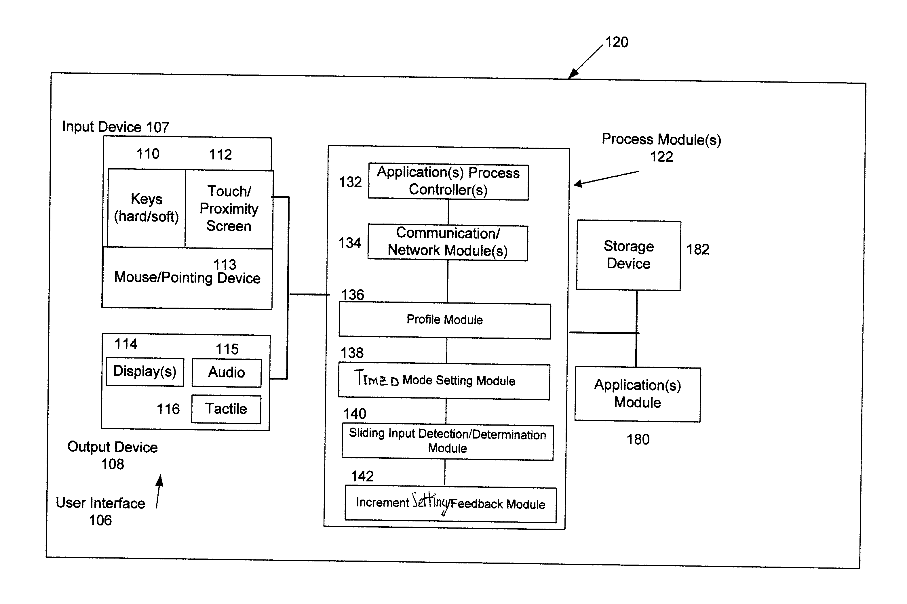
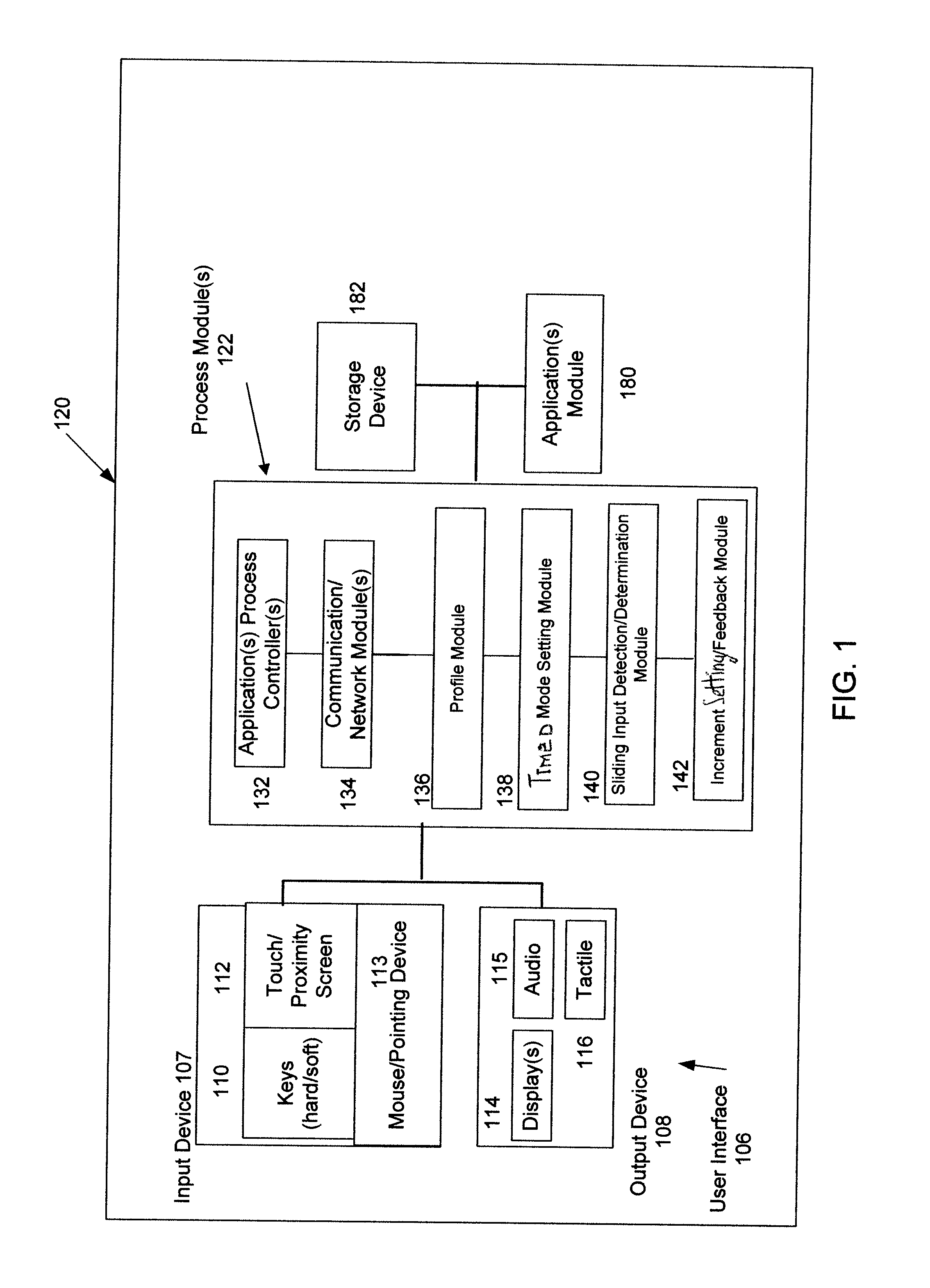
[0019]FIG. 1 illustrates one embodiment of a device 120 with which aspects of the disclosed embodiments can be applied. Although the disclosed embodiments will be described with reference to the embodiments shown in the drawings and described below, it should be understood that these could be embodied in many alternate forms. In addition, any suitable size, shape or type of elements or materials could be used.

[0020]The aspects of the disclosed embodiments are generally directed to allowing for adjusting and / or setting the expiration moment in a timed mode or profile with a few simple sliding movements or gestures on a touch sensitive area of a device 120. What is generally described herein as the “setting of a timed mode”, or the “setting of the Timed Silent profile” is applicable to any setting or adjustment of time or date in an application, such as for example, a clock or calendar application of the device 120. The term “expiration time” as used herein generally applies to the le...


PUM


Abstract

A method, apparatus, user interface and computer program product for using a device to detect a signal corresponding to a sliding input on a touch sensitive area of the device, the sliding input being for a time setting adjustment. A time unit corresponding to a start point of the sliding input is determined, and if the signal indicates that the sliding input is substantially in a first direction, a time setting of the corresponding time unit is increased by a pre-defined increment, and if the signal indicates that the sliding input is substantially in a second direction, the time setting of the corresponding time unit is decreased by a pre-defined increment. Feedback signals are provided at regular intervals of length, along the route of the sliding movement. Those feedback signals can be sensed or felt, which helps in using the device without looking all the time at the screen, which enables the eyes-free-operation of the device for most time settings, so that they can be made with a single hand; with the thumb of the hand which holds the device.

Description

BACKGROUND[0001]1. Field[0002]The aspects of the disclosed embodiments generally relate to communication devices and personal digital assistant (PDA) style devices, and in particular to a timed mode setting in a mobile device.[0003]2. Brief Description of Related Developments[0004]The typical mobile device, such as for example a mobile communication device, will have one or more operating modes or profiles. These can include for example, normal, silent, meeting, outdoor, pager and offline. The settings of mobile devices are typically grouped in these modes or profiles, where each different mode generally provides a number of different settings for the input and output functions and alerts of the device. Some of these settings can include, for example, a ringing tone, ringing type, ringing volume, message alert tone, email alert tone, vibrating alert, keypad tones, warning tones, alarm tones of appointments in a clock and / or calendar application, haptic feedback of the input interfac...

Claims


Application Information

Patent Timeline
IPC IPC(8): G06F3/041
CPCG06F3/04847G06F3/0485G06F3/048G06F3/04883G06F3/04855
Inventor KAURANEN, EERO M. J.
Owner NOKIA CORP
Learn More