
Eyewear with enhanced ballistic resistance

Active Publication Date: 2011-08-11
OAKLEY INC
View PDF98 Cites 55 Cited by
  • Summary
  • Abstract
  • Description
  • Claims
  • Application Information

AI Technical Summary

Benefits of technology

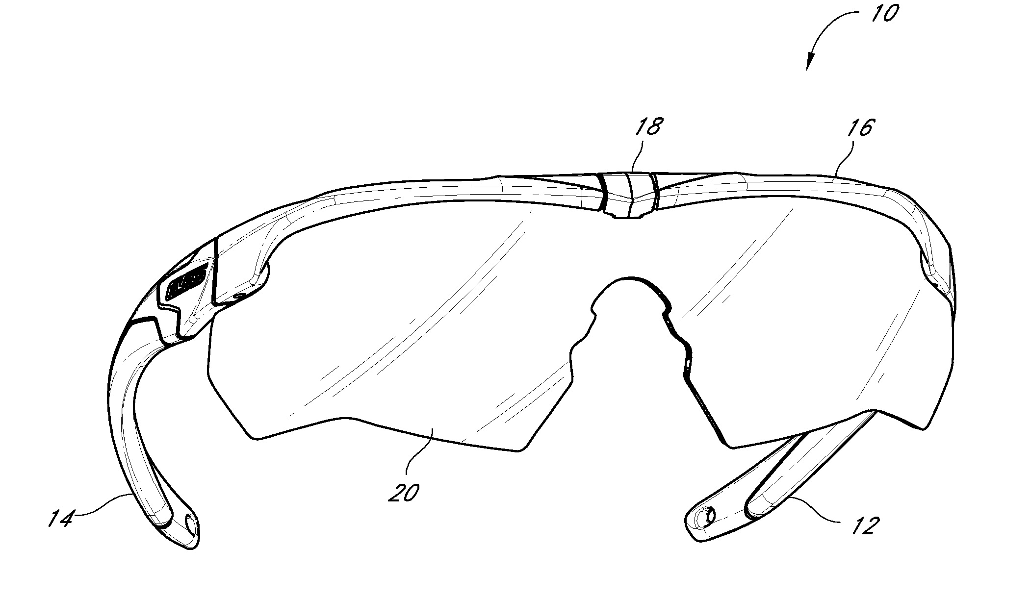
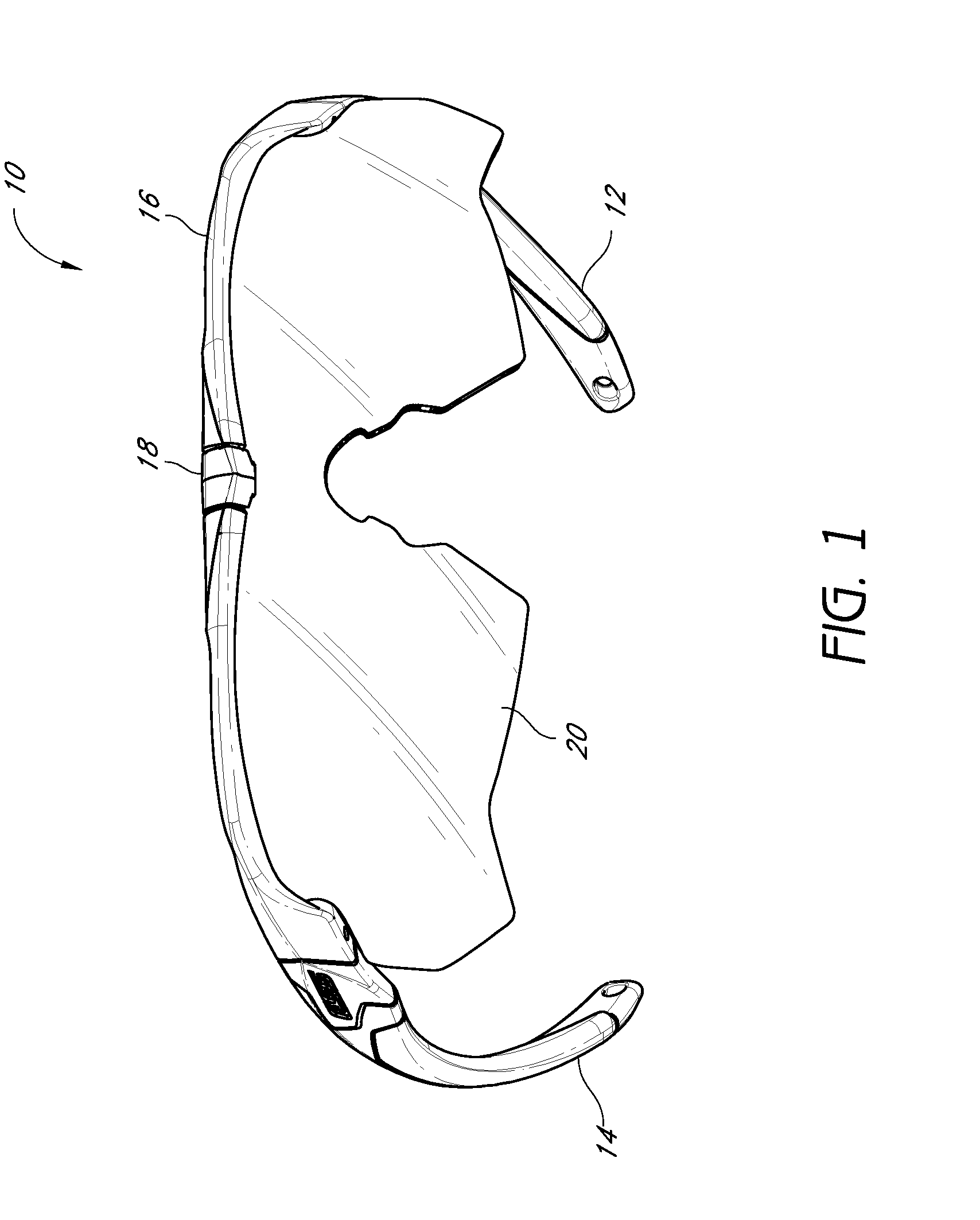
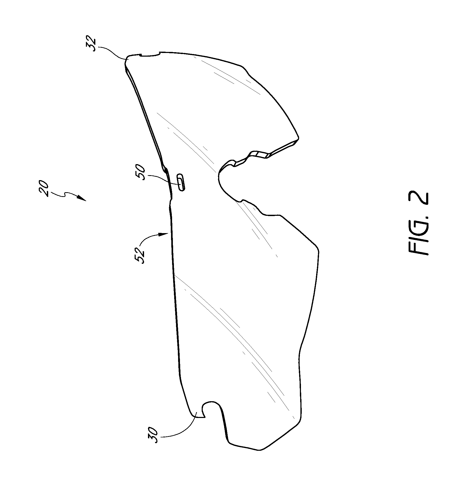
[0008]Embodiments disclosed herein provide, at least in part, a durable eyewear design for a goggle, eyeglass, or other eyewear that enables the lens to be securely retained by the frame of the eyewear. The eyewear can incorporate one or more retention components that may be used in conjunction with traditional lens mounting components, such as those in the systems disclosed in the patent references mentioned above. However, in some embodiments, the retention components can be used independent of traditional lens mounting components.
[0044]In some embodiments, the faceplate can define a centroid. The horizontal centroidal axis can pass through the centroid of the faceplate. In some embodiments, the horizontal centroidal axis can be configured to be parallel or coincident with an interception axis that passes through both pupils of the eyes of the wearer. Further, the horizontal centroidal axis can be positioned posteriorly relative to the lens of the eyewear. In some embodiments, the compressive forces can define a resultant force, and the first and second strap engagement mechanisms can be slidable within the first and second guide slots of the frame to maintain the orientation of the resultant force in a direction passing through or sufficiently near the centroid of the faceplate.

Problems solved by technology

Thus, impact from a ballistic event can cause the prior art lens to be dislodged, dislocated, or dismounted from the prior art frame.
Thus, at least one of the embodiments disclosed herein reflects the realization that prior art eyewear fails to provide sufficient ballistic resistance.

Method used


Image

  • Eyewear with enhanced ballistic resistance
  • Eyewear with enhanced ballistic resistance
  • Eyewear with enhanced ballistic resistance

Examples


Embodiment Construction

[0103]While the present description sets forth specific details of various embodiments, it will be appreciated that the description is illustrative only and should not be construed in any way as limiting. Additionally, although particular embodiments of the present inventions may be disclosed or shown in the context of unitary or dual lens eyewear systems, such embodiments can be used in both unitary and dual lens eyewear systems. Further, although embodiments disclosed herein can be used with eyeglasses that have removable and replaceable lenses, embodiments are also contemplated in which the eyeglasses are not intended to provide for removable or replaceable lenses.

[0104]Further, although particular embodiments may be disclosed or shown in the context of frames having partial orbitals, such embodiments can be used with frames having both full and partial orbitals. Retention components and structures in accordance with embodiments disclosed herein can also be utilized to retain a l...


PUM


Abstract

Eyewear is provided that can comprise a frame, a lens, and at least one retention component that can secure the lens relative to the frame. The frame can be configured to support at least one lens in a field of view of a wearer. The retention component can be supported by the frame and / or the lens and can be movable or fixed relative to the frame and / or the lens. In some embodiments, the retention component can slidably engage an engagement portion of the frame and / or the lens for preventing the lens from separating from the frame in response to a ballistic event. In some embodiments, the eyewear can comprise a faceplate and a pair of straps that attach to the frame of the eyewear in a manner that evenly distributes compressive stresses across the surface of the faceplate.

Description

CROSS-REFERENCE TO RELATED APPLICATIONS[0001]This application is a continuation-in-part of U.S. patent application Ser. No. 12 / 648,232, filed on Dec. 28, 2009, which claims the benefit of U.S. Provisional Application Nos. 61 / 143,645, filed Jan. 9, 2009, and 61 / 266,804, filed on Dec. 4, 2009, the entireties of each of which are incorporated herein by reference.BACKGROUND[0002]1. Field of the Inventions[0003]The present inventions relate generally to mounting systems for eyewear, and more specifically to methods and apparatuses for mounting an optical lens in a manner that provides excellent ballistic resistance and lens stability.[0004]2. Description of the Related Art[0005]A wide variety of improvements have been made in recent years in the eyewear field, particularly with respect to eyewear intended for use in active sports or as fashion sunglasses. These eyewear designs accomplish a variety of functional advantages, such as maximizing interception of peripheral light, reducing opt...

Claims


Application Information

Patent Timeline
IPC IPC(8): G02C5/04G02C3/00
CPCA61F9/025A61F9/027G02C1/04G02C2200/08G02C5/2263G02C2200/06G02C3/003F41H1/00F41H1/02
Inventor BELBEY, JASONOLDHAM, STEVEMORITZ, HANS KARSTENHUTCHISON, JASONMCCORMICK, CHAD
Owner OAKLEY INC
Learn More