
LED Luminaire for Display Cases

a technology of led luminaires and display cases, which is applied in the direction of lighting and heating apparatus, lighting support devices, lighting applications, etc., can solve the problems of requiring the replacement of the entire bulb, the electrodes of fluorescent bulbs are easily burnt out or broken, and the limited life of fluorescent bulbs used in such applications, so as to achieve the effect of reducing heat transfer from the luminair

Active Publication Date: 2011-08-18
ABL IP HLDG
View PDF100 Cites 48 Cited by
  • Summary
  • Abstract
  • Description
  • Claims
  • Application Information

AI Technical Summary

Benefits of technology

The patent describes a lighting luminaire that uses LEDs and a reflector to direct and diffuse light. The luminaire can be attached to a shelf or retrofitted into an existing luminaire. The reflector can be adjusted to change the direction of light exiting the luminaire. The LED mounting portion and reflector can be separate components or integrally formed. The luminaire also includes fins to dissipate heat generated by the LEDs and a void or offset to further promote heat dissipation. The patent also describes the use of a thermal insulation pad and water shedding surfaces to minimize heat transfer and protect the LEDs from condensation. The technical effects of the patent include improved lighting in refrigerated display cases and energy-efficient lighting solutions.

Problems solved by technology

However, the fluorescent bulbs used in such applications have limited life and must be replaced often.
The electrodes in fluorescent bulbs are easily burnt out or broken, requiring that the entire bulb be replaced.
Moreover, the glass bulbs themselves are susceptible to breakage.
A lamp provided at the top of the unit illuminates the products positioned near the top of the case, but fails to adequately illuminate those products positioned lower within the case.
Yet, the use of multiple lamps increases the energy and thus cost needed to adequately illuminate the case.
In this way, such LEDs provide non-uniform, direct illumination of merchandise.

Method used


Image

  • LED Luminaire for Display Cases
  • LED Luminaire for Display Cases
  • LED Luminaire for Display Cases

Examples


Embodiment Construction

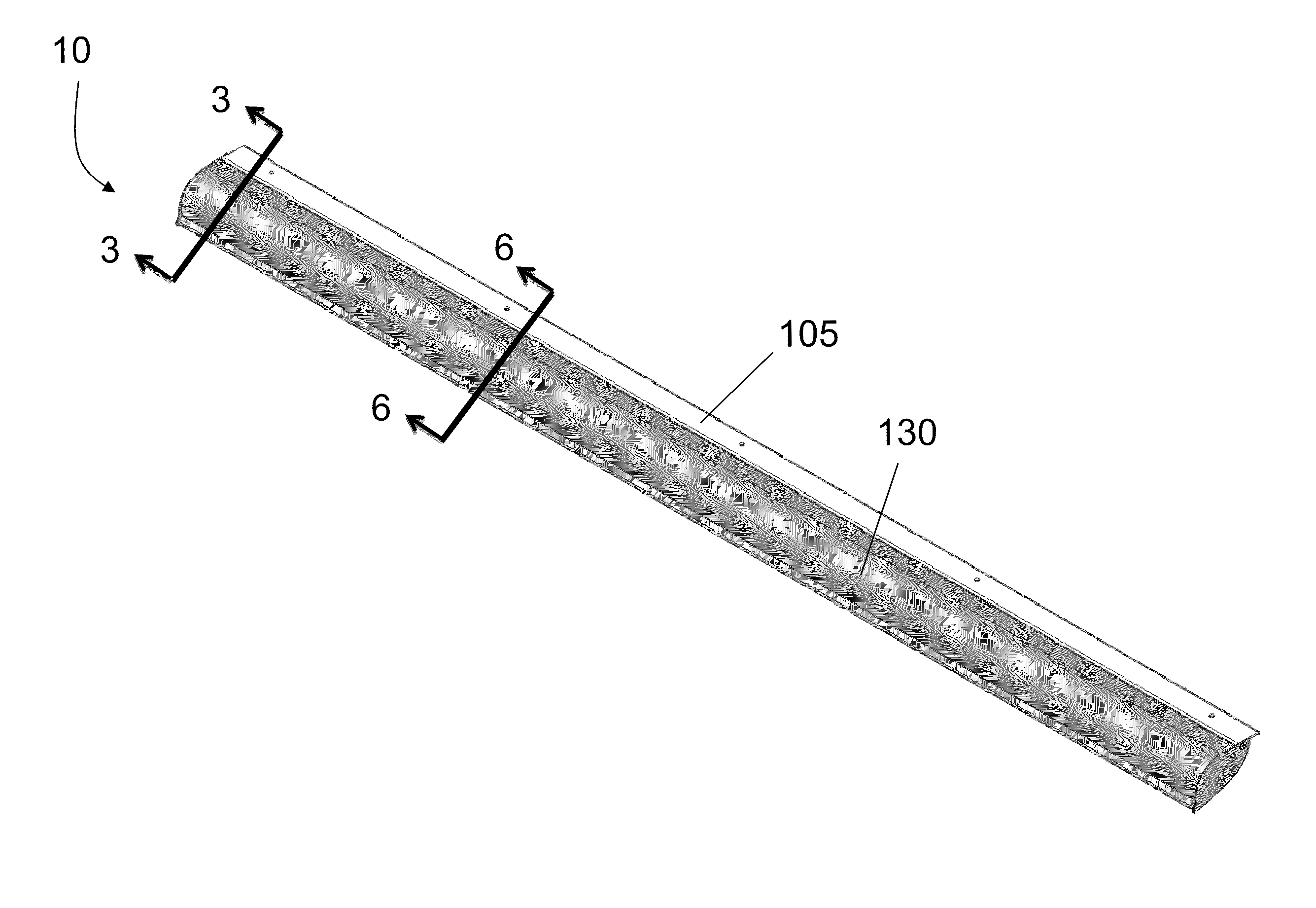
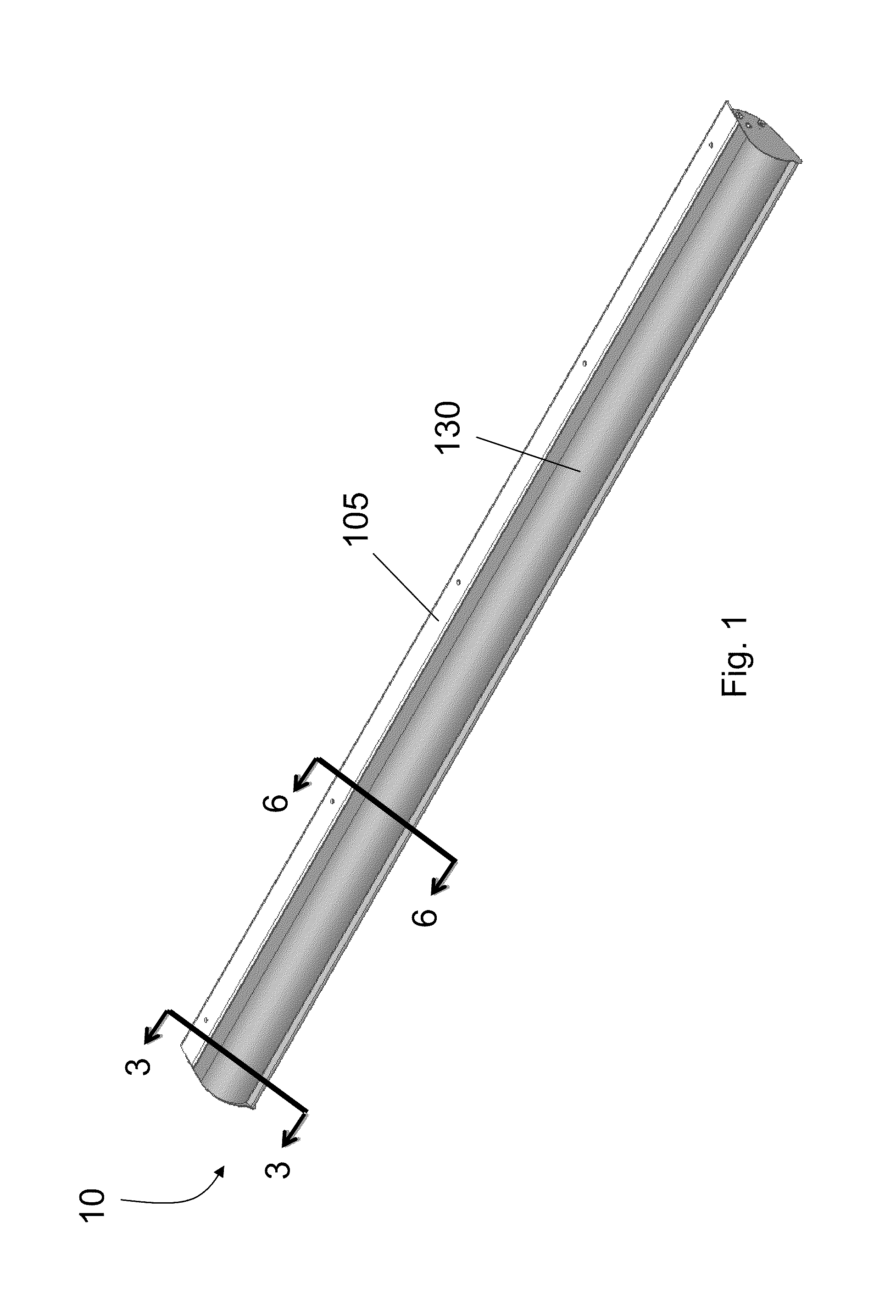
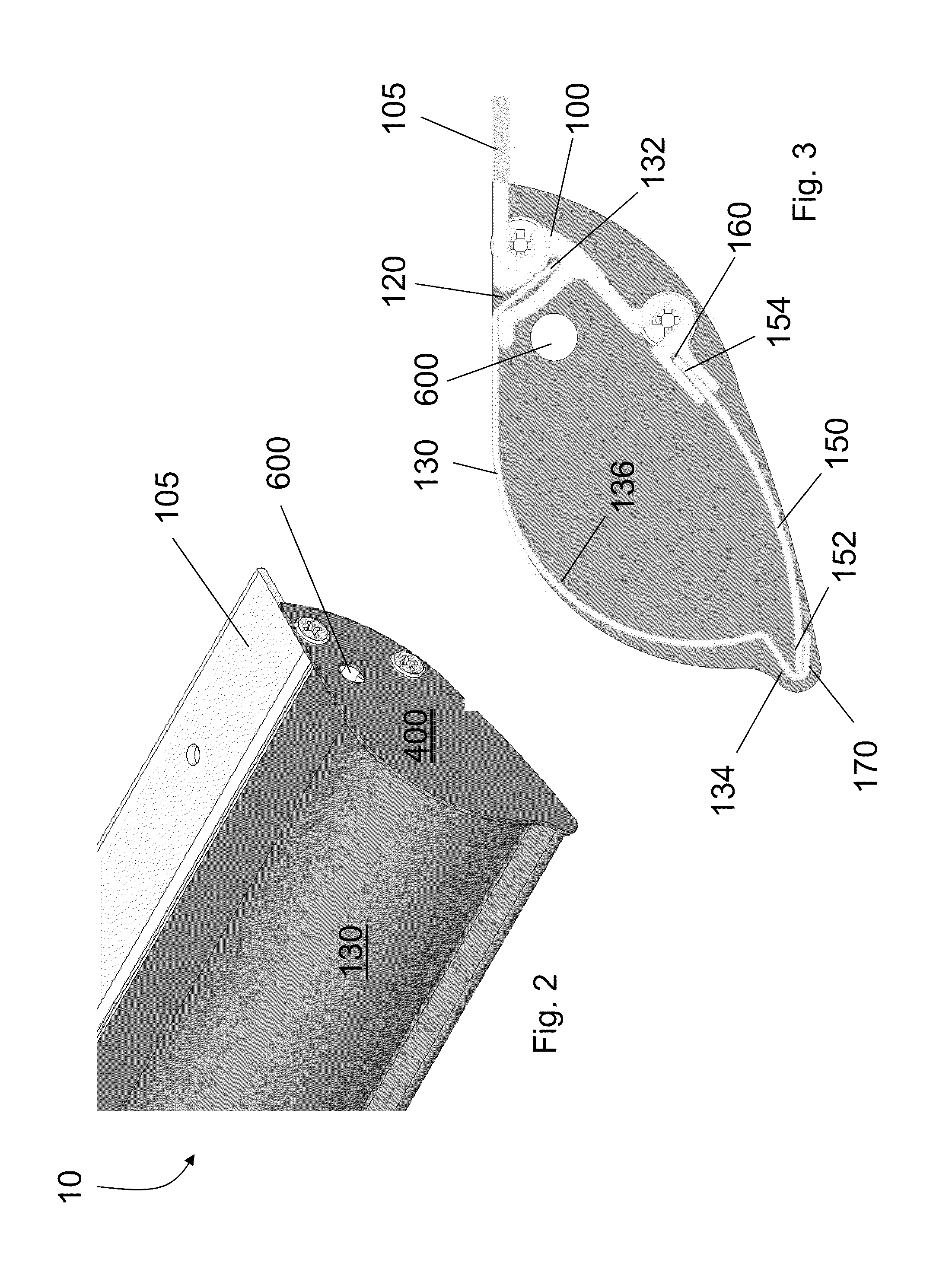
[0006]In one embodiment, a lighting luminaire includes an LED mounting portion comprising a plurality of LEDs mounted thereon, a reflector, and a lens. The LED mounting portion and reflector are sized and arranged to form a reflective cavity for diffusing and directing light from the plurality of LEDs through the lens and out of the luminaire.

[0007]In an embodiment, the LED mounting portion and reflector are attached to each other as separate components or are integrally formed. In another embodiment, if the LED mounting portion and reflector are separate components the LED mounting portion can include a slot for receiving the reflector and attaching the reflector thereto.

[0008]In yet other embodiments, the lens is held in place in the luminaire between the LED mounting portion and the reflector or is mounted directly on the LED mounting portion over the plurality of LEDs. In a further embodiment, the lens is clear or is refractive with a symmetrical, asymmetrical or non-symmetrical...


PUM

PropertyMeasurementUnit
depthaaaaaaaaaa
energyaaaaaaaaaa
heataaaaaaaaaa

Abstract

A lighting luminaire for use in a refrigerated display case includes an LED mounting portion comprising a plurality of light emitting diodes (“LEDs”) mounted thereon, a reflector, and a lens. The LED mounting portion and reflector are sized and arranged to form a reflective cavity for diffusing and directing light from the plurality of LEDs through the lens and out of the luminaire. The LED mounting portion and reflector are either attached to each other as separate components or are integrally formed. The lens is held in place in the luminaire between the LED mounting portion and the reflector or is mounted directly on the LED mounting portion over the plurality of LEDs. The LED mounting portion and / or reflector have a reflective surface for reflecting light emitted by the LEDs. Methods for retrofitting an existing luminaire in a refrigerated display with an LED luminaire are also provided.

Description

CROSS REFERENCE TO RELATED APPLICATION[0001]This application is a continuation-in-part of U.S. patent application Ser. No. 12 / 840,704, filed Jul. 21, 2010, which claims the benefit of U.S. Provisional application Ser. No. 61 / 271,428, filed Jul. 21, 2009, the entire contents of which are incorporated herein by reference.FIELD OF THE INVENTION[0002]The present invention relates to light-emitting diode (“LED”) luminaires, and in particular LED luminaires adaptable for use in refrigerated display cases.BACKGROUND OF THE INVENTION[0003]Display cases, including refrigerated display cases, historically have used fluorescent sources to light the interior of the case. However, the fluorescent bulbs used in such applications have limited life and must be replaced often. The electrodes in fluorescent bulbs are easily burnt out or broken, requiring that the entire bulb be replaced. Moreover, the glass bulbs themselves are susceptible to breakage.[0004]The fluorescent bulbs have been positioned ...

Claims


Application Information

Patent Timeline
Patent Type & Authority Applications(United States)
IPC IPC(8): F21V7/00F21V5/00
CPCA47F3/001F21V29/76F21V7/0008F21V7/16F21V7/22F21V15/013F21V17/16F21V21/02F21V25/00F21V29/004F21W2131/305F21W2131/405F21Y2101/02F21Y2103/003F21V29/15F21V29/505F21V29/507F21V29/75F21S4/008F21V29/70F21S4/28F21Y2103/10F21Y2115/10F21V7/24F21V7/28
Inventor MARQUARDT, CRAIG EUGENEIBANEZ, MIGUEL ANGELSICKING, DANIEL EDWARDMILLER, MICHAEL RAY
Owner ABL IP HLDG
Learn More