Apparatus and method to repair the junction of a sewer main line and lateral pipe

a sewer main and lateral pipe technology, applied in the direction of adhesives, thin material processing, lamination, etc., can solve the problems of liner not being able to cure to fully repair the junction, water leakage, damage or leakage at the junction between the lateral pipe and the sewer main

Active Publication Date: 2011-08-25
LMK TECH LLC
View PDF4 Cites 52 Cited by
  • Summary
  • Abstract
  • Description
  • Claims
  • Application Information

AI Technical Summary

Benefits of technology

[0007]It is therefore a principal object, feature, or advantage of the present invention to provide an improved apparatus and method for repairing the juncture of a main sewer line with a lateral pipe.
[0008]Another object, feature, or advantage of the present invention is to provide an improved method and apparatus for repairing the juncture of a main line and lateral pipe in the presence of water leaking into the juncture.
[0009]Another object, feature, or advantage of the present invention is to provide an improved method and apparatus for repairing the juncture of a lateral with a main line which may be accomplished from the sewer main line.
[0010]Another object, feature, or advantage of the present invention is to provide an improved method and apparatus for repairing both the juncture of a lateral with a main line and the lateral line itself.
[0011]Yet, another object, feature, or advantage of the present invention is to make a seal between the main and lateral pipe on the outside of the pipe junction and not reduce the inner diameter of the pipe more than approximately the thickness of the pipe liner.

Problems solved by technology

Damage or leaking can occur at the junction between the lateral pipe and the main pipe, which is generally known as one of the weakest points in a collection sewer system.
At the main and lateral junction, however, the damaged areas often allow the leakage of water.
Water tends to seep through the fractures and joints of the junction, and will interact with the resin impregnated liner, and in turn, the liner may not be able to cure to fully repair the junction.
A disadvantage to injecting grout first and then inserting a cured-in-place pipe (CIPP) liner is the time and labor necessary to insert two different pieces of equipment in the main pipe and to robotically position those devices with multiple lateral connections.
The result is a much greater cost, as the multiple processes would take more time and potentially more people to repair the different areas of the pipe.

Method used


Image

  • Apparatus and method to repair the junction of a sewer main line and lateral pipe
  • Apparatus and method to repair the junction of a sewer main line and lateral pipe
  • Apparatus and method to repair the junction of a sewer main line and lateral pipe

Examples


Embodiment Construction

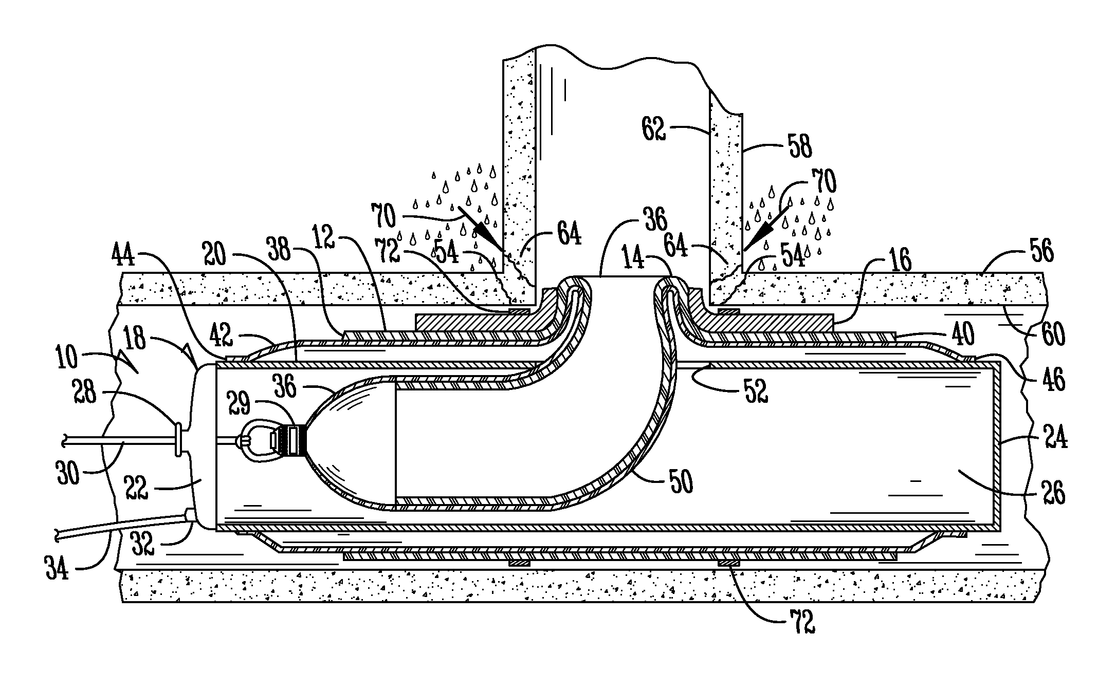
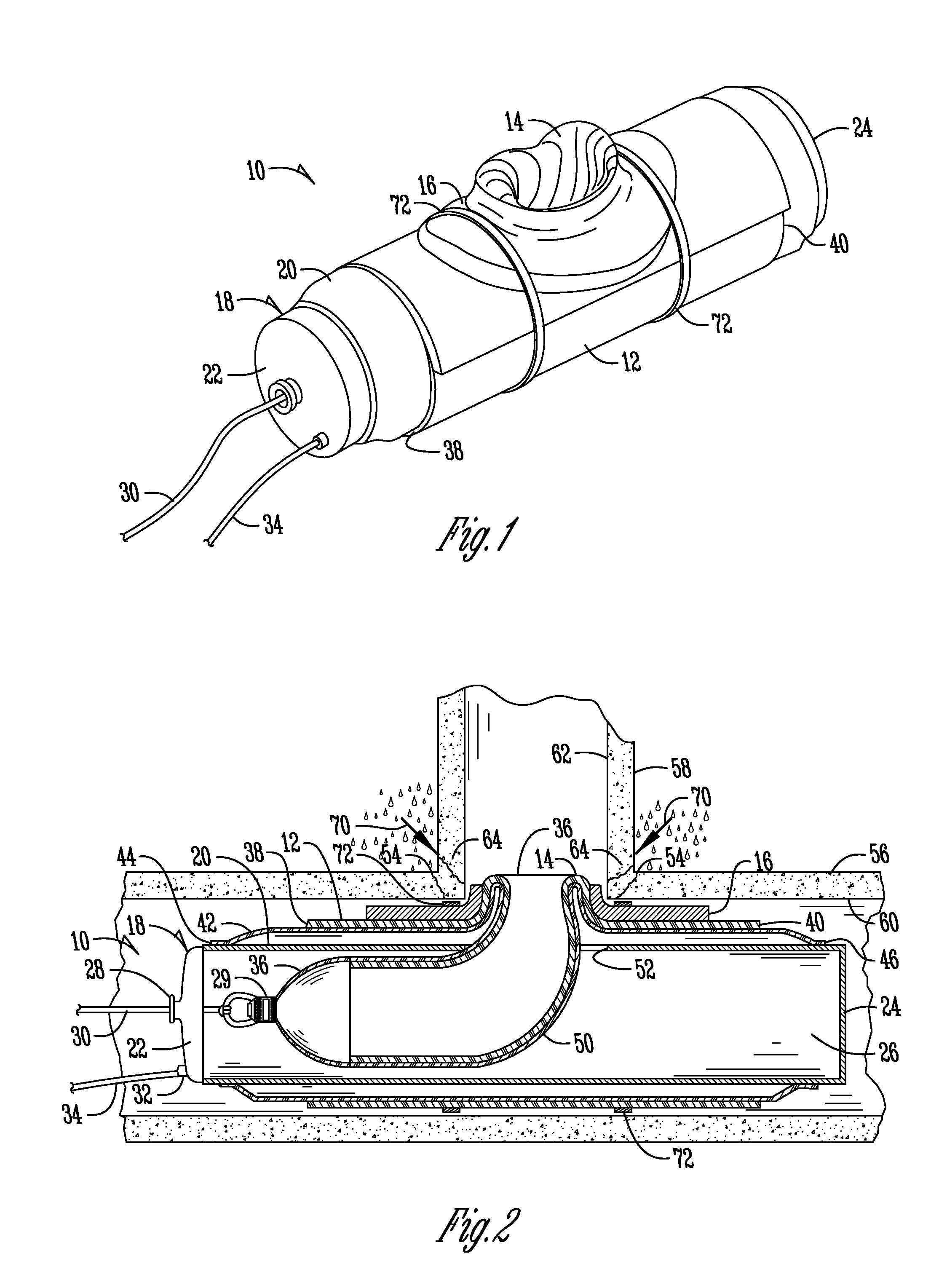
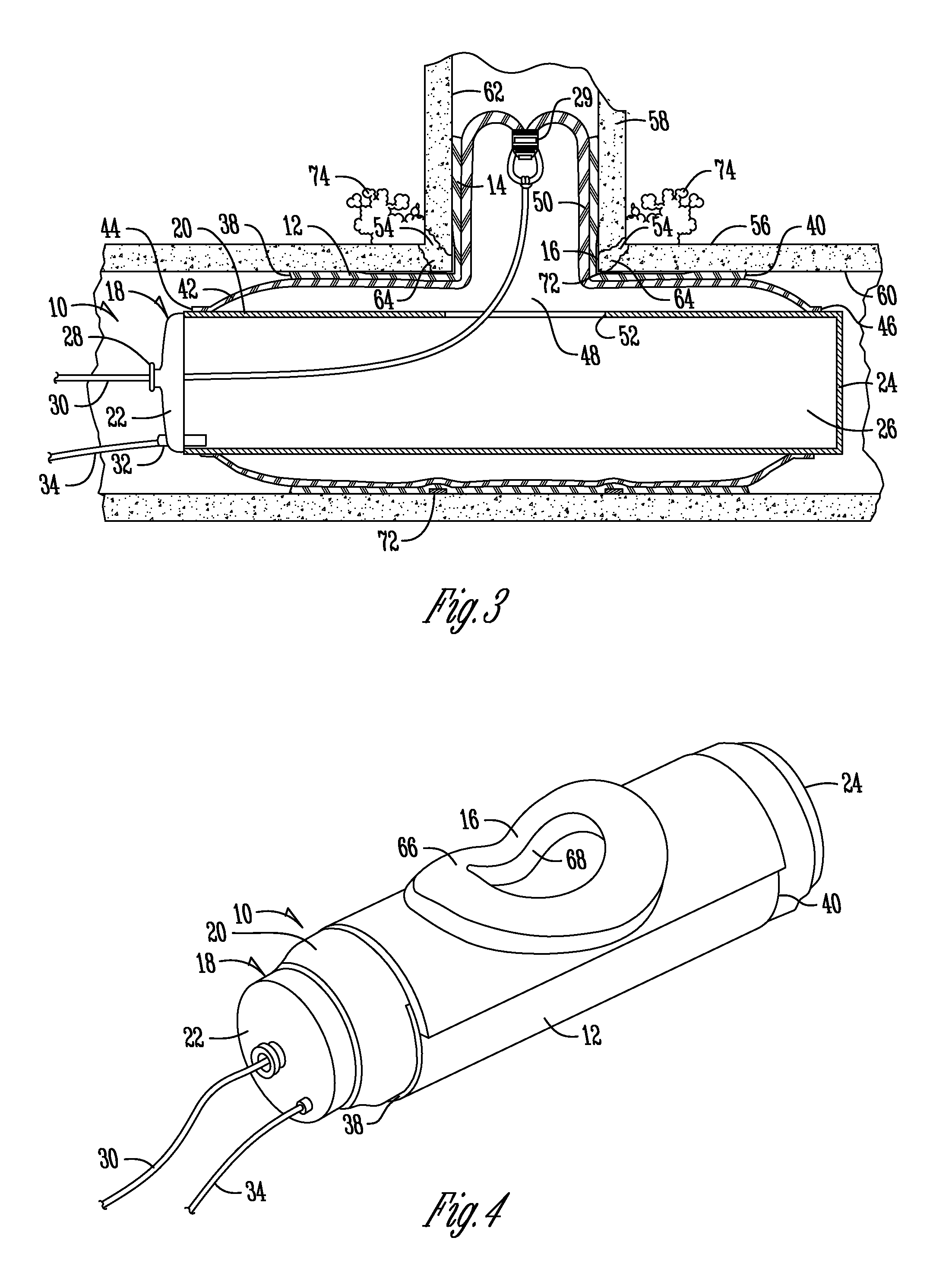
[0024]Referring to FIGS. 1-3, a liner assembly is generally designated by the numeral 10. Liner assembly 10 includes a launcher device 18 having mounted thereto a T-shaped or Y-shaped liner and bladder. The liner consists of a main liner member 12 and a lateral liner tube 14. In one embodiment, the main liner member 12 is a tube, but it can also be other shapes as well, such as a collar. The bladder consists of a main bladder tube 42, comprising a first end 44, a second end 46, and a main bladder tube opening 48, and a lateral bladder tube 50. In the particular configurations shown in FIGS. 1-3, the liner and bladder are T-shaped, but they can also be Y-shaped to accommodate a lateral pipe line that intersects with a main pipe line at an oblique angle.

[0025]Launcher device 18 includes side walls 20, a first end 22, a second end 24, all of which form a launcher device cavity 26. The first end of the launcher device 22 includes a line inlet 28 through which a line 30 extends. Line 30 ...


PUM

PropertyMeasurementUnit
hydrophobicaaaaaaaaaa
hydrophilicaaaaaaaaaa
tubular shapeaaaaaaaaaa

Abstract

A liner assembly and method for lining a damaged pipe junction between a main and lateral pipe is provided. The liner assembly includes a main liner member and a lateral liner tube. A collar disposed near the juncture between the main liner member and lateral liner tube is impregnated with a liquid hydrophobic or hydrophilic material capable of curing in a flexible or rigid state with the material expanding in the presence of water. The hydrophobic or hydrophilic material can also be applied without the use of the collar. When the liner assembly is pressed against the main and lateral pipes, a portion of the hydrophilic or hydrophobic material is forced into the damaged pipe junction.

Description

FIELD OF THE INVENTION[0001]The present invention relates generally to sewer pipe line repair, and more particularly to an improved method and apparatus for repairing the juncture of a sewer main pipe and a lateral pipe.BACKGROUND OF THE INVENTION[0002]Prior methods for repairing damaged portions of pipelines include moving a liner tube impregnated with a liquid material capable of curing and hardening to a position within the pipe where the damaged portion is located. The liner tube is installed by pulling, pushing, or everting the liner into the host pipe. Once the liner is positioned within the host pipe, it is pressurized, usually by an inflation bladder, causing the liner to press against the interior wall of the host pipe, and the liner is cured by applying heat, such as steam or hot water. These liners can also be cured at ambient temperatures by a chemical mixture which generates an exothermic reaction. The liner tube forms an interior liner in the pipe for the pipeline bein...

Claims


Application Information

Patent Timeline
Patent Type & Authority Applications(United States)
IPC IPC(8): B29C73/04F16L55/16
CPCF16L55/1651F16L55/1654Y10T156/1033F16L55/179Y10T428/139F16L55/1656F16L55/265B29C63/28B29C63/341B29C63/36B29C65/484B29C65/525B29C66/301B29C66/5221B29C66/52241B29C66/634
Inventor KIEST, JR., LARRY W.
Owner LMK TECH LLC
Why Eureka
Try Eureka