Metatarsal joint shape for prosthetic foot and control mechanism and system for same

Active Publication Date: 2011-08-25
OSSUR HF
View PDF43 Cites 8 Cited by
  • Summary
  • Abstract
  • Description
  • Claims
  • Application Information

AI Technical Summary

Benefits of technology

[0008]An improved prosthetic foot designed for providing metatarsal functionality is described. In one embodiment, the prosthetic foot includes a generally plate-like foot member that extends along a longitudinal axis between an anterior end, which can correspond to a toe portion, and a posterior end, which can correspond to a heel portion. The prosthetic foot can include an elongate groove that can extend across t

Problems solved by technology

There is much difficulty in developing a prosthetic foot that mimics the natural function of human toes.
The challenges may be even greater when trying to replicate a human toe that can account for other physical modifications of the prosthetic foot.
When the heel hei

Method used


Image

  • Metatarsal joint shape for prosthetic foot and control mechanism and system for same
  • Metatarsal joint shape for prosthetic foot and control mechanism and system for same
  • Metatarsal joint shape for prosthetic foot and control mechanism and system for same

Examples


Embodiment Construction

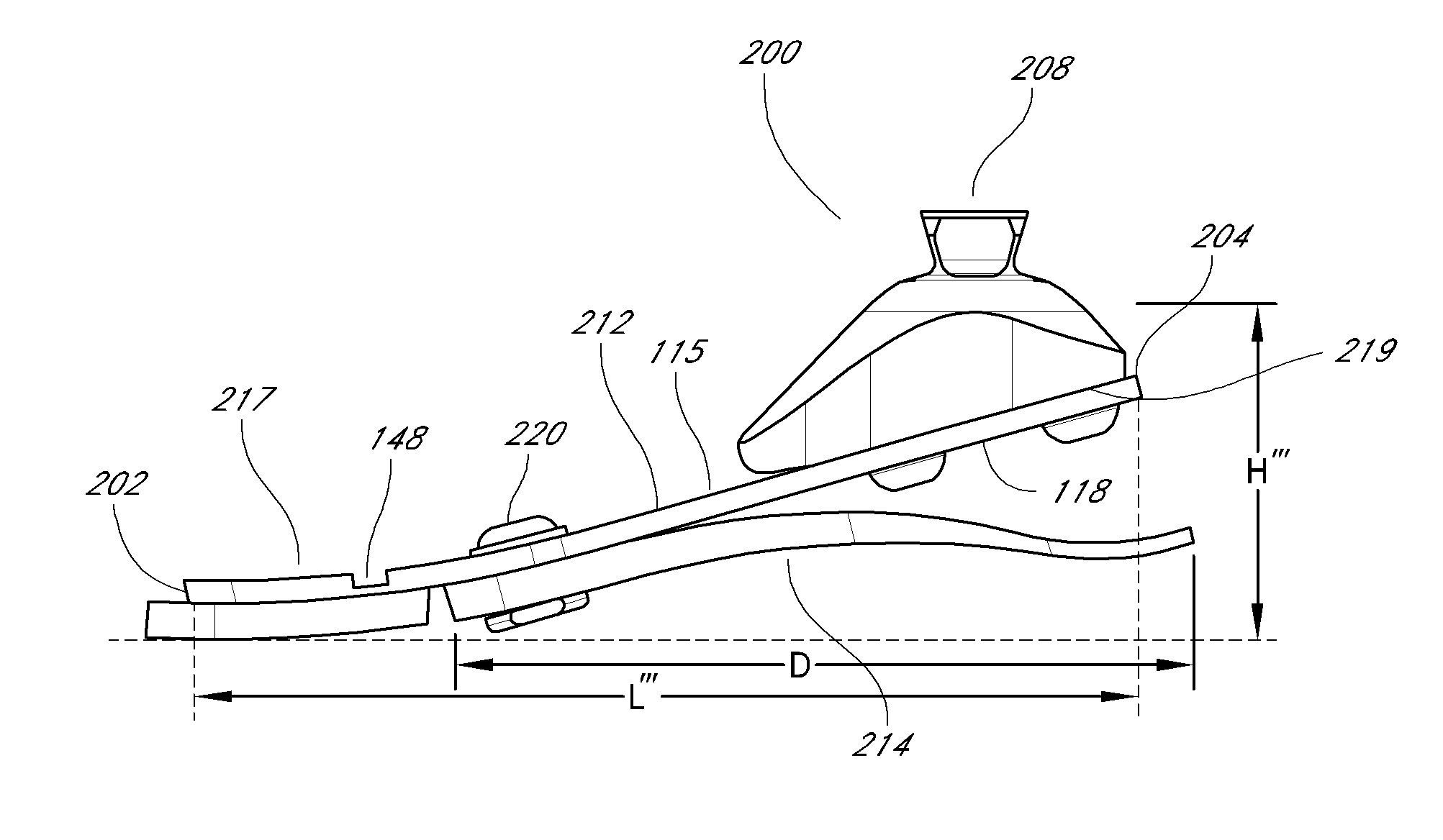
[0022]Improved prosthetic feet are described that are capable of providing metatarsal functionality and mimicking the natural function of human feet. In particular, the prosthetic feet described herein include a metatarsal joint shape and control mechanism and system that can include a metatarsal hinge that provides metatarsal functionality. The prosthetic feet described herein advantageously assist in achieving the goals described above, including providing balance, improved push-off patterns and thrust during gait, even following heel-height adjustment.

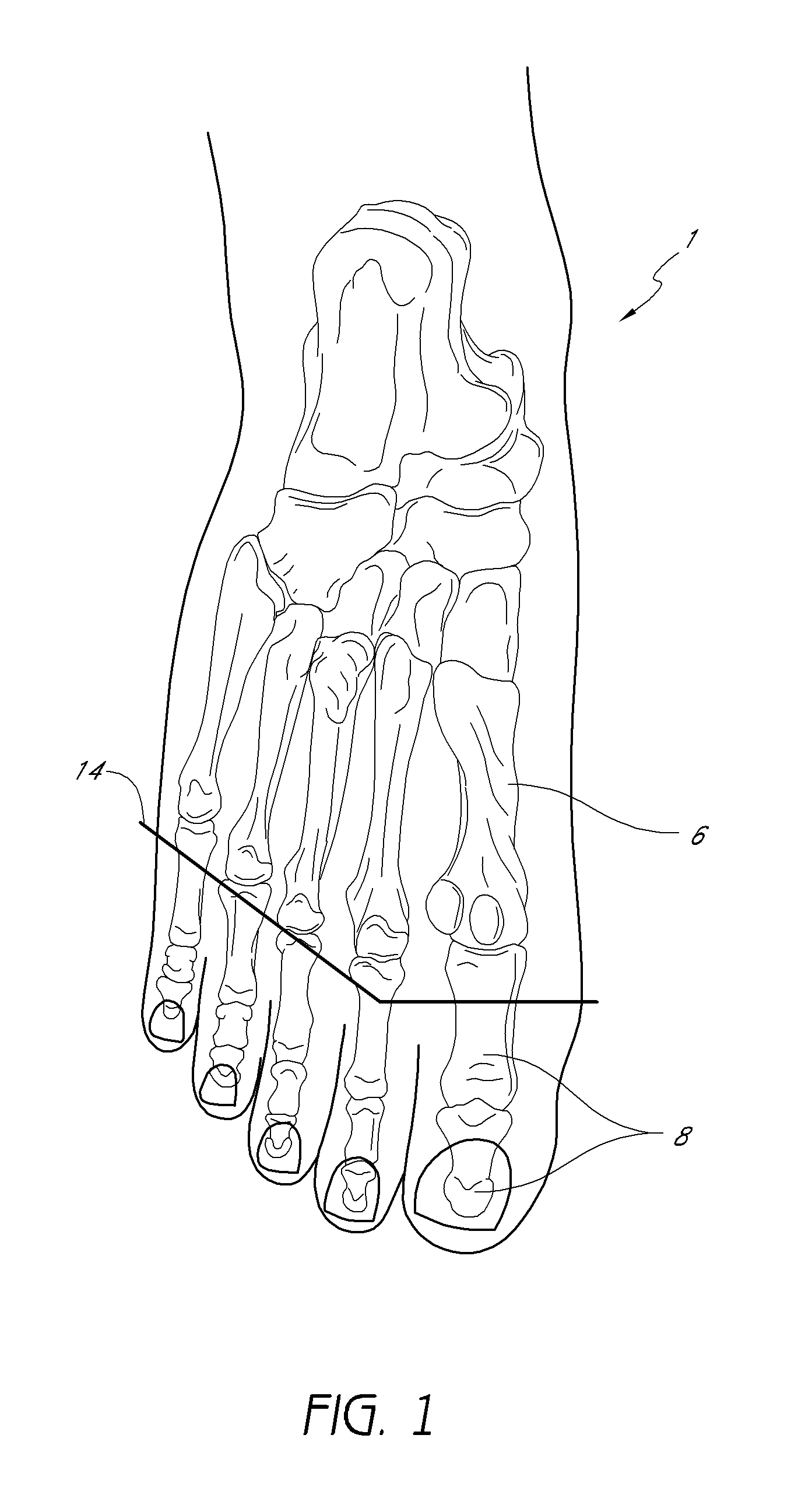
[0023]FIG. 1 illustrates an upper cross-sectional view of a human foot. The human foot 1 serves as a mechanical structure having bones, joints, muscles, tendons and ligaments. Bones in the human foot include metatarsal bones 6 and shorter phalanges 8 that form the toes. Metatarsophalangeal joints exist between the metatarsal bones 6 and phalanges 8. These joints assist in providing joint articulation of the phalanges 8 relative to t...


PUM


Abstract

A prosthetic foot can include a plate-like foot member extending along a longitudinal axis between an anterior end generally corresponding to a toe portion of a foot to a posterior end, and a metatarsal hinge comprising an elongate groove extending between medial and lateral edges of the foot member. The elongate groove can intersect the longitudinal axis of the foot member, and can be positioned along the length of the foot member at a location generally corresponding to a metatarsal region of the foot. The metatarsal hinge can also comprise a plurality of elongate apertures that extend completely through the foot member, or a plurality of recessed channels that extend only partially through the foot member, or a combination thereof.

Description

RELATED APPLICATIONS[0001]This application claims priority under 35 U.S.C. §119(e) as a nonprovisional of U.S. Provisional App. No. 61 / 307,267 (Atty Docket No. OSSUR.115PR), filed Feb. 23, 2010. This application is also related to U.S. patent application Ser. No. 12 / 509,055 (Atty Docket No. OSSUR.050CP1C2), filed Jul. 24, 2009, which is a continuation of U.S. patent application Ser. No. 10 / 987,940 (Atty Docket No. OSSUR.050CP1), filed Nov. 12, 2004, now issued as U.S. Pat. No. 7,846,213, which is a continuation-in-part of U.S. patent application Ser. No. 10 / 944,436 (Atty Docket No. OSSUR.050A), filed Sep. 17, 2004, now issued as U.S. Pat. No. 7,347,877, which claims priority to Provisional App. No. 60 / 575,142 (Atty Docket No. OSSUR.050PR), filed May 28, 2004. The entire contents of each of these references is hereby incorporated by reference.BACKGROUND OF THE INVENTION[0002]1. Field of the Invention[0003]The present application relates in certain embodiments to prosthetic feet. In p...

Claims


Application Information

Patent Timeline
IPC IPC(8): A61F2/66
CPCA61F2/6607A61F2002/5056A61F2/66A61F2002/665A61F2002/6678A61F2002/6635
Inventor CLAUSEN, ARINBJÖN V.GUNNSTEINSSON, LÁRUS
Owner OSSUR HF
Why Eureka
Try Eureka