Method and system for automated lighting control and monitoring
What is AI technical title?
AI technical title is built by Patsnap AI team. It summarizes the technical point description of the patent document.
a technology for lighting control and monitoring, applied in the field of lighting systems, can solve the problems of increasing scrutiny of expenditures related to acquiring, maintaining, operating, and administering lighting systems, and achieve the effect of improving the efficiency of lighting system maintenance and operation
Active Publication Date: 2011-09-08
LSI INDS
View PDF4 Cites 67 Cited by
Summary
Abstract
Description
Claims
Application Information
AI Technical Summary
This helps you quickly interpret patents by identifying the three key elements:
Problems solved by technology
Method used
Benefits of technology
Benefits of technology
[0003]Embodiments of the present invention are directed to automated control of lighting systems at individual-light-fixture, local, regional, and larger-geographical-area levels. One embodiment of the present invention comprises a hierarchical lighting-control system including an automated network-control center that may control up to many millions of individual lighting fixtures and lighting elements, regional routers interconnected to the network-control center or network-control centers by public communications networks, each of which controls hundreds to thousands or more of individual light fixtures, and light-management units, interconnected to regional routers by radio-frequency communications and / or power-line communications, each of which controls components within a lighting fixture, including lighting elements, associated ballasts, sensors, and other devices.
Problems solved by technology
Lighting systems for public roadways, thoroughfares, and facilities, private and commercial facilities, including industrial plants, office-building complexes, schools, universities, and other such organizations, and other public and private facilities account for enormous yearly expenditures of energy and financial resources, including expenditures for lighting-equipment acquisition, operation, maintenance, and administration.
Because of rising energy costs, falling tax-generated funding for municipalities, local governments and state governments, and because of cost constraints associated with a variety of different enterprises and organizations, expenditures related to acquiring, maintaining, servicing, operating, and administering lighting systems are falling under increasing scrutiny.
Method used
Image
Click on the blue label to locate the original text in one second.
Reading with bidirectional positioning of images and text.
Examples
Embodiment Construction
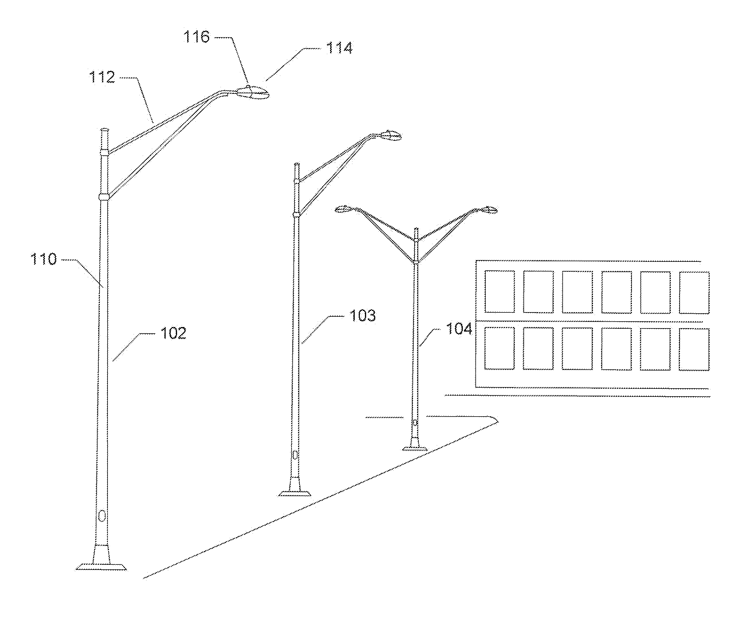
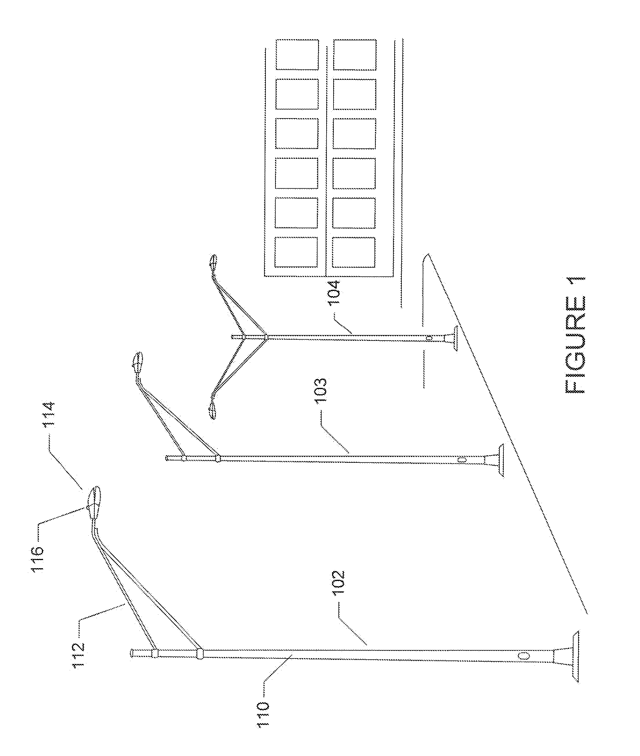
[0020]There are many different types of lighting fixtures, lighting elements, or luminaires, and lighting applications. FIG. 1 illustrates a portion of a traditional lighting system observed in parking lots, along thoroughfares and roadways, and within industrial sites, school facilities, and office-building complexes. Such lighting systems commonly employ street-light fixtures, such as street-light fixtures 102-104 in FIG. 1. Each street-light fixture includes a rigid, vertical pole 110 and arms or brackets 112, through which internal electrical wiring runs, that together support one or more lighting units 114. Each lighting unit generally includes one or more lighting elements and associated electrical ballasts that limit voltage drops across, and current drawn by, lighting elements and that buffer voltage and / or current surges and shape the input voltage or current in order to provide a well-defined output voltage or current for driving the lighting elements. Many different types...
PUM
Abstract
Embodiments of the present invention are directed to automated control of lighting systems at individual-light-fixture, local, regional, and larger-geographical-area levels. One embodiment of the present invention comprises a hierarchical lighting-control system including an automated network-control center that may control up to many millions of individual lighting fixtures and lighting elements, regional routers interconnected to the network-control center or network-control centers by public communications networks, each of which controls hundreds to thousands of individual light fixtures, and light-management units, interconnected to regional routers by radio-frequency communications and / or power-line communications, each of which controls components within a lighting fixture, including lighting elements, associated ballasts, sensors, and other devices.
Description
TECHNICAL FIELD[0001]The present invention is related to lighting systems, and, in particular, to automated control systems for controlling and monitoring individual lighting elements, lighting elements associated with individual fixtures, and arbitrarily sized groups of lighting fixtures located across local, regional, and larger geographical areas.BACKGROUND OF THE INVENTION[0002]Lighting systems for public roadways, thoroughfares, and facilities, private and commercial facilities, including industrial plants, office-building complexes, schools, universities, and other such organizations, and other public and private facilities account for enormous yearly expenditures of energy and financial resources, including expenditures for lighting-equipment acquisition, operation, maintenance, and administration. Because of rising energy costs, falling tax-generated funding for municipalities, local governments and state governments, and because of cost constraints associated with a variety...
Claims
Application Information
Patent Timeline
Application Date:The date an application was filed.
Publication Date:The date a patent or application was officially published.
First Publication Date:The earliest publication date of a patent with the same application number.
Issue Date:Publication date of the patent grant document.
PCT Entry Date:The Entry date of PCT National Phase.
Estimated Expiry Date:The statutory expiry date of a patent right according to the Patent Law, and it is the longest term of protection that the patent right can achieve without the termination of the patent right due to other reasons(Term extension factor has been taken into account ).
Invalid Date:Actual expiry date is based on effective date or publication date of legal transaction data of invalid patent.
Patent Type & AuthorityApplications(United States)

