Liquid Dispensing Device Comprising A Peristaltic Pump

Inactive Publication Date: 2011-09-15
THE GILLETTE CO
View PDF48 Cites 13 Cited by
  • Summary
  • Abstract
  • Description
  • Claims
  • Application Information

AI Technical Summary

Benefits of technology

[0008]Other features and advantages of the invention will be apparent from the description and drawings, and from the claims. Methods of using said device are also provided.

Problems solved by technology

However, many of these wet razors that dispense liquid during use are awkward to operate and cumbersome to hold because of the size and shape needed to accommodate a peristaltic pump.
Moreover, some even require multiple parts and electrical power from a wall outlet, limiting the portability of the hand held device.
Furthermore, with multiple parts, when stored and during operation, these hand held devices occupy valuable space in bathrooms that are typically limited in size.
This pulling and tugging by the smaller peristaltic pumps is believed to cause displacement of the tube, as well as wear and tear on the material of the tube, ultimately reducing the life of the device.
Further, for the system disclosed in U.S. Pat. No. 7,699,552, although a pump with a moveable pressing member is disclosed, the pressing movement by the user can be prone to uncertain dispensing and excessive downward pressing or dragging force on the roller.

Method used


Image

  • Liquid Dispensing Device Comprising A Peristaltic Pump
  • Liquid Dispensing Device Comprising A Peristaltic Pump
  • Liquid Dispensing Device Comprising A Peristaltic Pump

Examples


Embodiment Construction

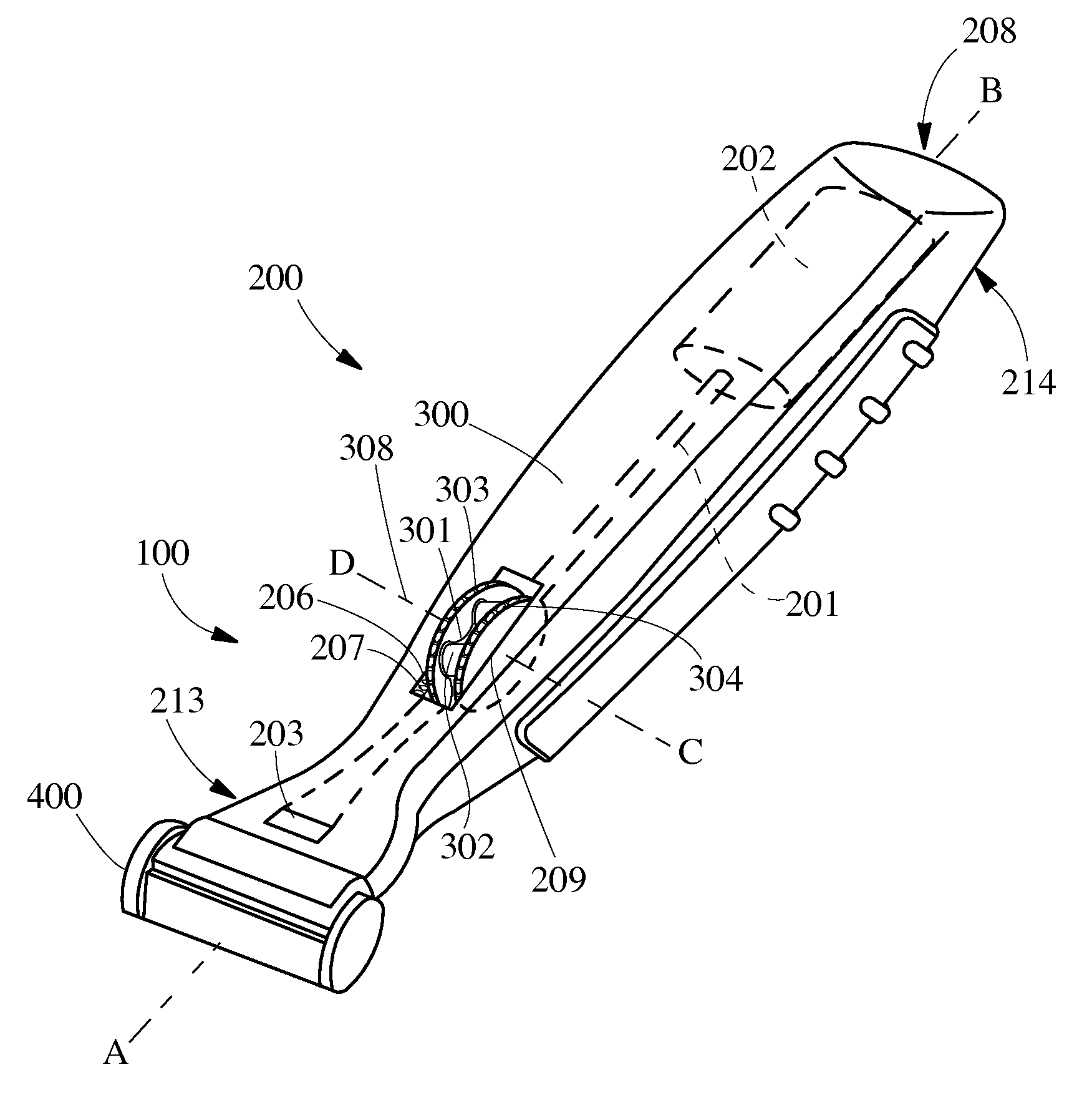
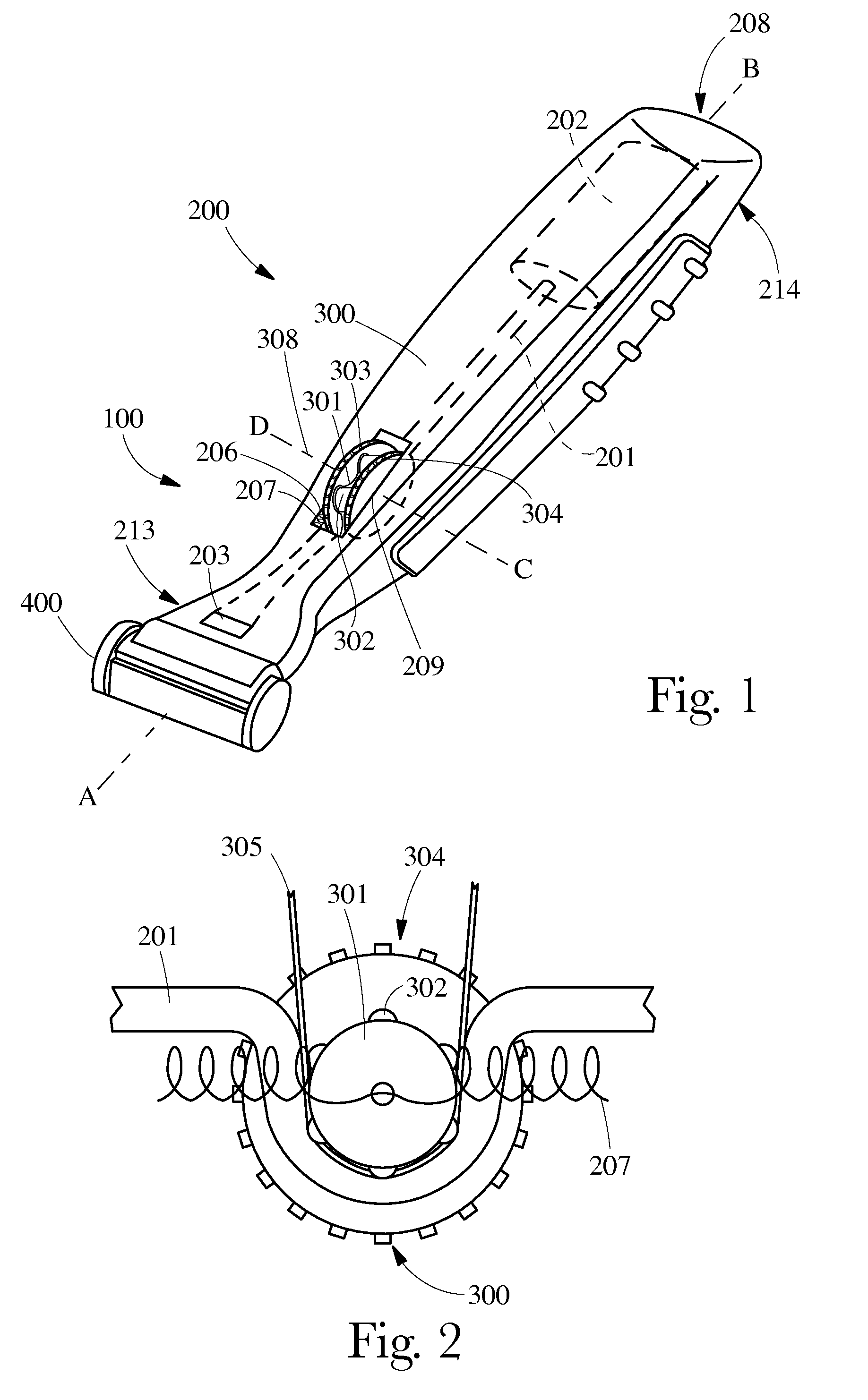
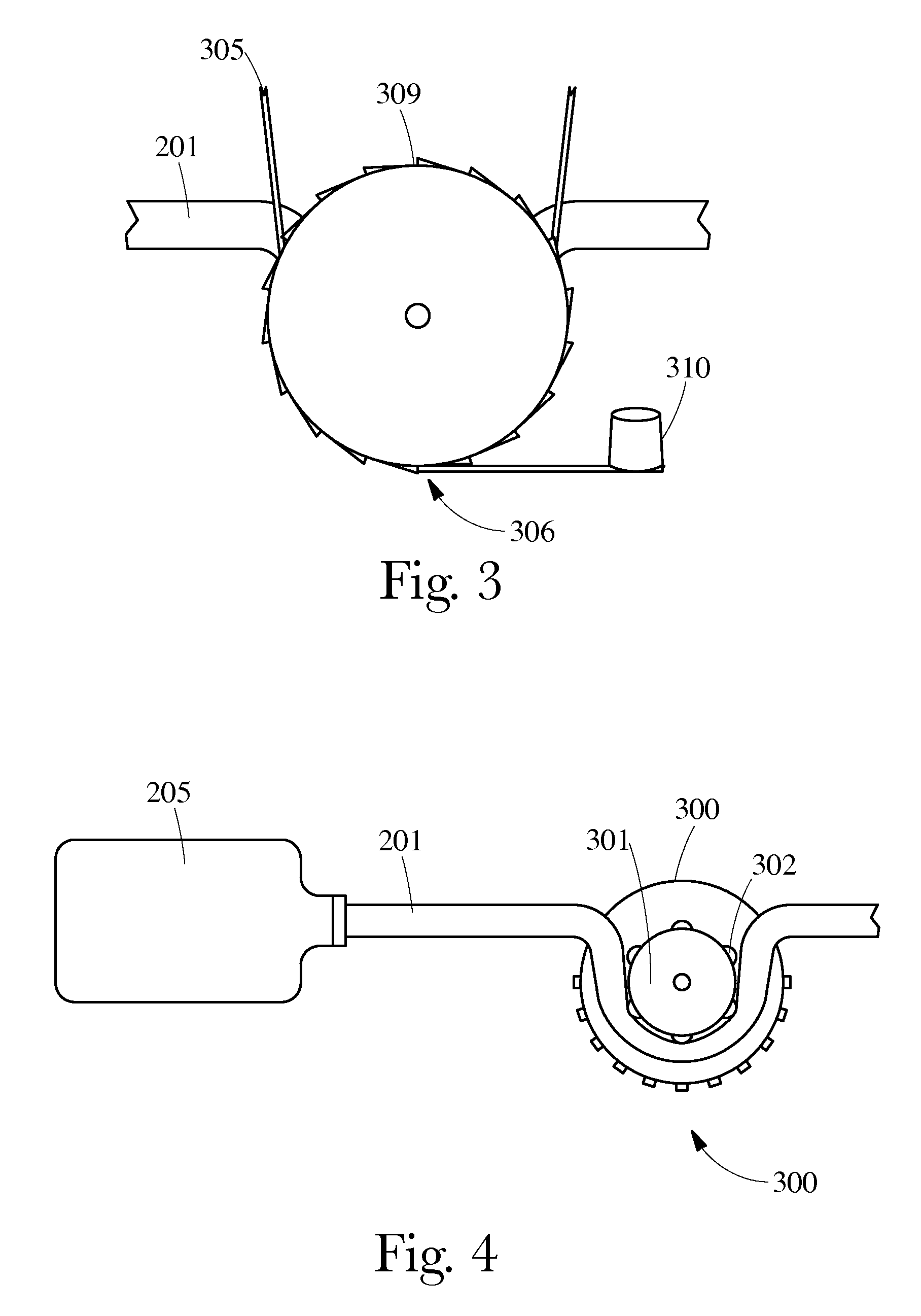
[0015]FIGS. 1-6 show a hand held device (100) capable of dispensing fluid during the hair removal process (such as shaving), comprising, a peristaltic pump (300), and a device head (400). The device head (400) may be a shaving cartridge, which includes a guard and an elastomeric member disposed on the guard, or a scraping surface. Nonlimiting examples of suitable device heads are disclosed in U.S. Pat. Nos. 7,197,825, 6,298,558, 6,161,288. FIG. 1 shows a head which is a razor head (100). FIG. 6 shows a head which is a toothbrush head (115).

[0016]FIG. 1 provides a perspective view of the hand held device (100). The handle (200) has a proximal end (213) and a distal end (212) and is adapted to hold a device head (400). The device head (400) may be permanently affixed on handle (200), or may be releasably engaged from the handle (200). Nonlimiting examples of suitable handles are disclosed in U.S. Pat. D533,684, U.S. Pat. No. 5,918,369, and U.S. Pat. No. 7,168,173. This disengagement o...


PUM


Abstract

The invention features a hand held device that dispenses fluid during operation. The hand held device includes a handle and a device head operably engaged thereto. The handle has a proximal end forming a product dispensing aperture, a distal end forming a cavity for housing a fluid, a supply channel in fluid communication with the cavity and the product dispensing aperture, a peristaltic pump physically engaged with the supply channel, said peristaltic pump comprising a rotating actuator having an central axis which has a maximum radial movement of the rotating actuator of up to about 15 mm. Actuation of the peristaltic pump displaces fluid from the cavity to the product dispensing aperture.

Description

CROSS REFERENCE TO RELATED APPLICATIONS[0001]This application claims the benefit of U.S. Provisional Application No. 61 / 340,289 filed Mar. 15, 2010.BACKGROUND OF THE INVENTION[0002]Liquid dispensing hand held devices, such as razors and toothbrushes, are known. For example, razors that dispense liquid have been disclosed in U.S. Pat. No. 4,653,188, U.S. Pat. Nos. 5,701,674 and 5,070,611, and U.S. Applications 2009 / 0235530, 2009 / 0211099, 2009 / 0183371, 2008 / 0216322, and 2006 / 0272154. Disclosed in these and other publications are various wet shaving product configurations that include systems for conveying a shaving preparation during shaving, e.g., a lubricating fluid, from a reservoir incorporated in the razor structure in the form of a hollowed out razor handle or even an aerosol can that acts as a razor handle, to a dispensing location near the head of the razor. A number of more recent wet shaving razors have cartridges that are moveably mounted, in particular, pivotable, relative...

Claims


Application Information

Patent Timeline
IPC IPC(8): B26B21/44
CPCB26B21/446B26B19/40
Inventor ROCKELL, BARRY KEITHJOLLEY, WILLIAM OWENSALEMME, JAMES LEO
Owner THE GILLETTE CO
Why Eureka
Try Eureka