Method And System For Controlling A 3D Processor Using A Control List In Memory

a control list and memory technology, applied in the field of communication systems, can solve the problems of not being suitable for certain applications, such as mobile applications, and being very computationally intensive in operating on video data

Active Publication Date: 2011-09-15
AVAGO TECH INT SALES PTE LTD
View PDF18 Cites 65 Cited by
  • Summary
  • Abstract
  • Description
  • Claims
  • Application Information

AI Technical Summary

Benefits of technology

[0025]FIG. 5 is a block diagram that illustrates an exemplary control list and control sub-list that may be utilized to manage 3D pipeline processing, in accordance with an embodiment of the inve

Problems solved by technology

Operating on video data, however, may be very computationally intensive because of the large amounts of data that need to be constantly moved around

Method used


Image

  • Method And System For Controlling A 3D Processor Using A Control List In Memory
  • Method And System For Controlling A 3D Processor Using A Control List In Memory
  • Method And System For Controlling A 3D Processor Using A Control List In Memory

Examples


Embodiment Construction

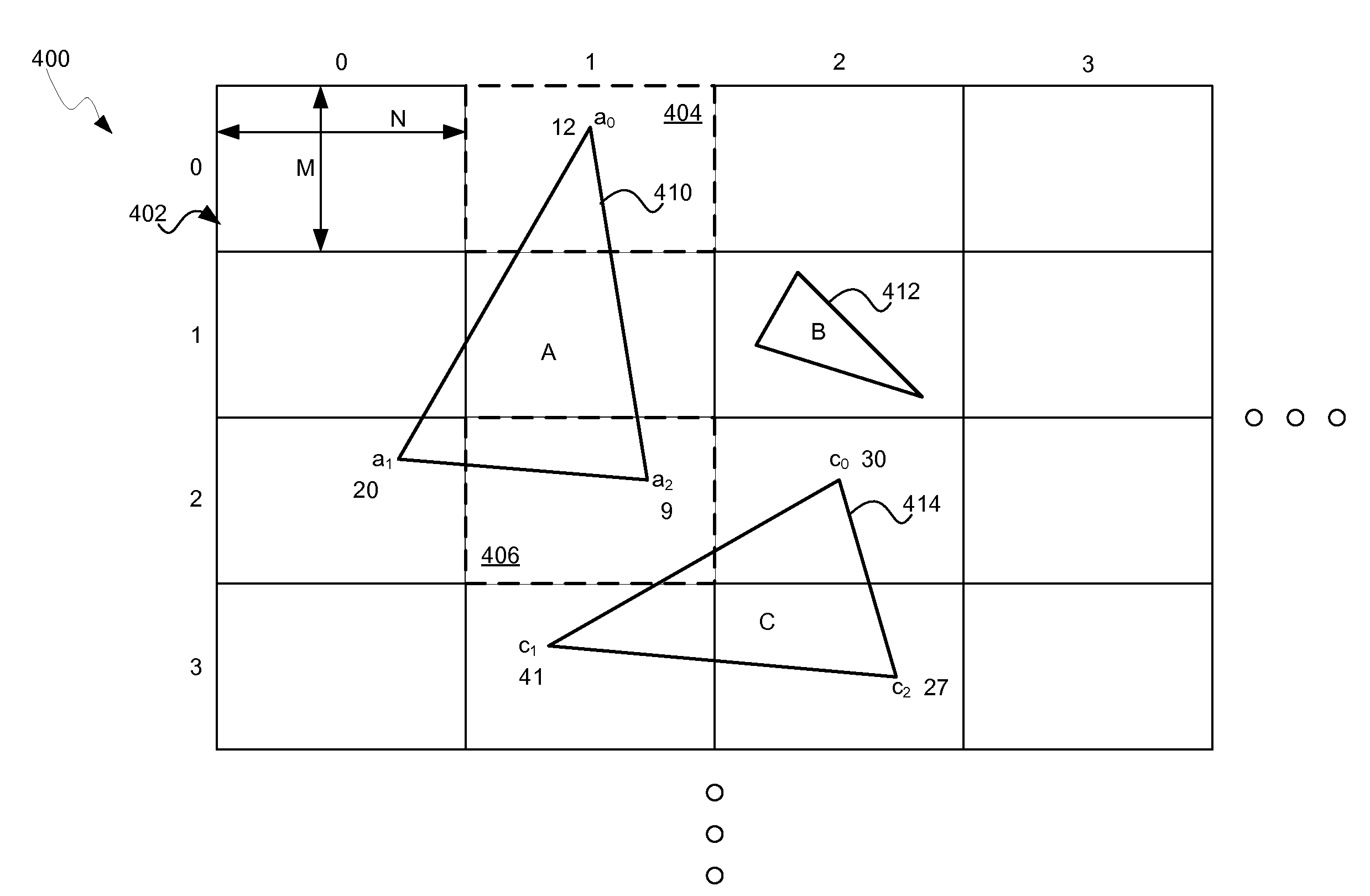
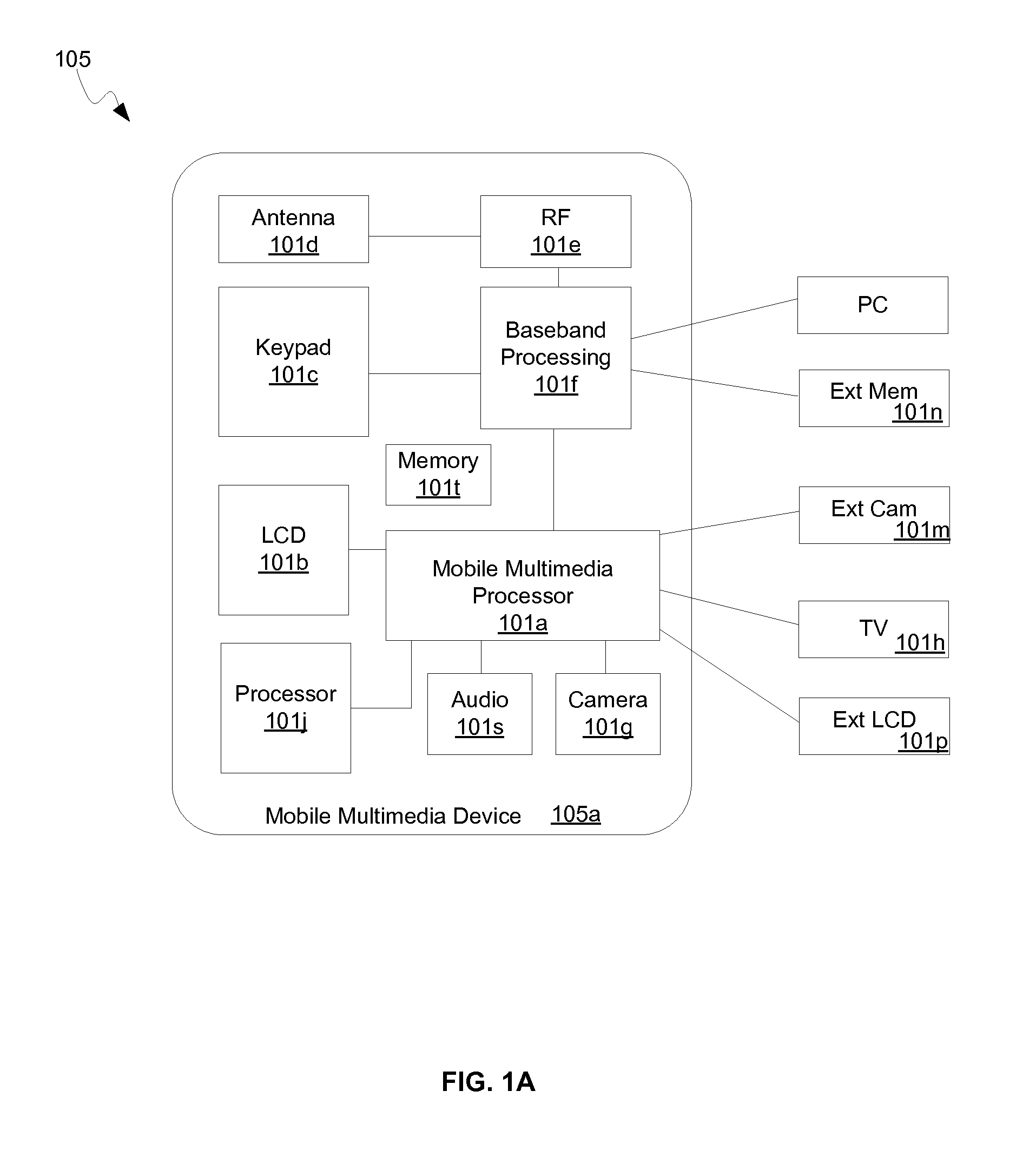
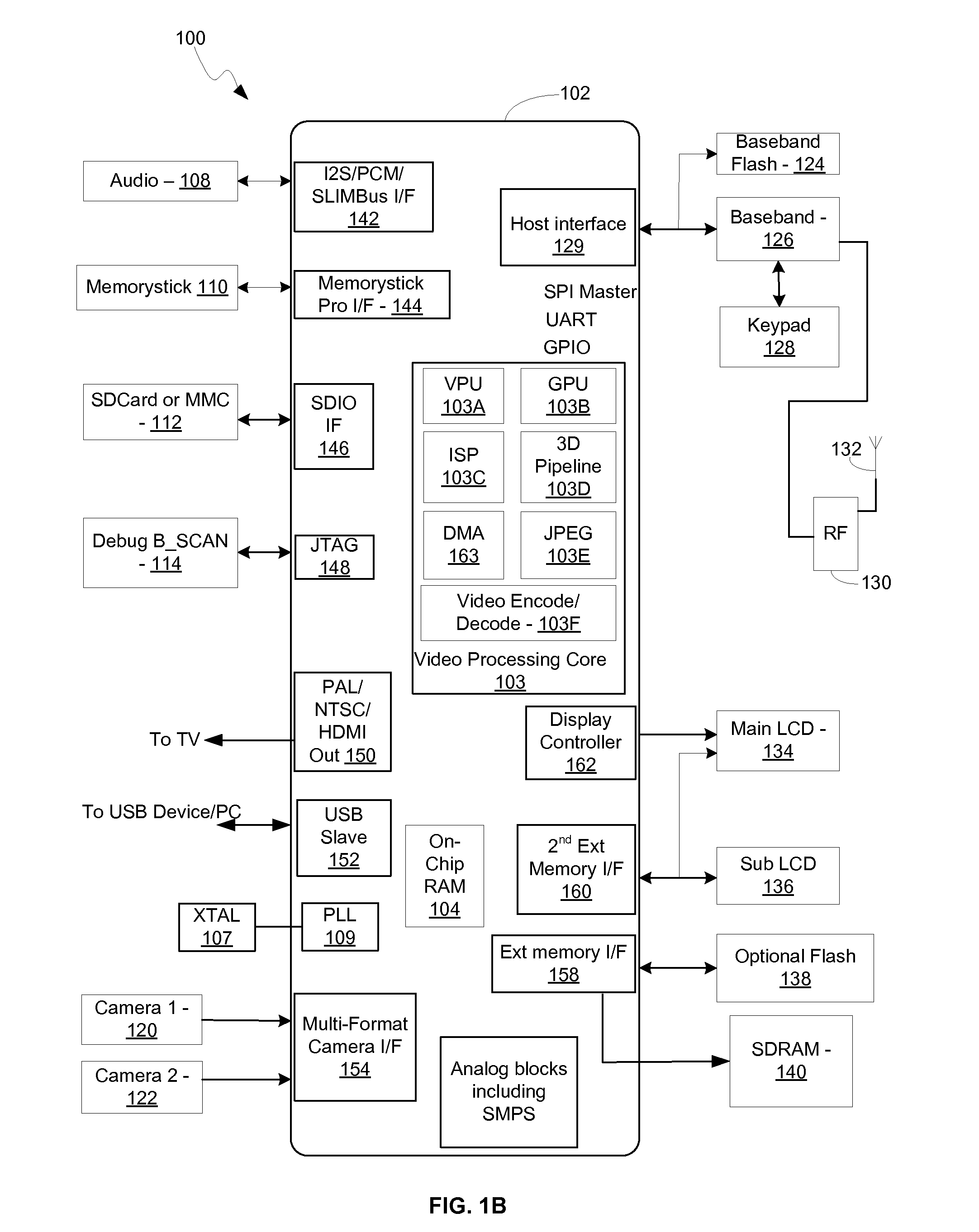
[0027]Certain embodiments of the invention can be found in a method and system for controlling a 3D processor using a control list in memory. One or more processors and / or circuits in a graphics processing device may be operable to generate one or more control lists that may correspond to 3D graphics to be processed. Records within the one or more control lists may comprise primitive data for the 3D graphics and / or pointers to the primitive data. In addition, the records may comprise control data for processing the primitive data. Processing of the 3D graphics may be controlled utilizing the records within the generated control lists. The graphics processing device may comprise one or more parallel processors that may process portions of the 3D graphics in parallel. The processing may be controlled utilizing one or more tags that may correspond to one or more of the records within the generated control lists. The 3D graphics may be processed on a tile by tile basis, wherein a tile m...


PUM


Abstract

A graphics processing device generates control lists for controlling processing of 3D graphics. Control lists comprise primitive data for the 3D graphics, pointers to primitive data and control data. Tags that correspond to records within the control lists may be utilized for the control of processing. The graphics processing device may comprise a 3D pipeline comprising parallel processors. Processing is performed on a tile by tile basis and comprises a tile binning phase and/or a tile rendering phase. The two phases of processing may be performed in parallel on different sets of data. Control lists comprise a main list and/or sub-lists, for example, tile lists. Control lists may comprise links to other lists. Processing control may advance through the control lists without interaction from a driver and/or from a processor that is external to the graphics processing device.

Description

CROSS-REFERENCE TO RELATED APPLICATIONS / INCORPORATION BY REFERENCE[0001]This application makes reference to, claims priority to, and claims the benefit of U.S. Provisional Application Ser. No. 61 / 312,988, filed on Mar. 11, 2010 which is incorporated herein by reference in its entirety.[0002]This application also makes reference to:[0003]U.S. patent application Ser. No. ______ (Attorney Docket Number 21161US01) which was filed on ______;[0004]U.S. patent application Ser. No. ______ (Attorney Docket Number 21162US01) which was filed on ______;[0005]U.S. patent application Ser. No. ______ (Attorney Docket Number 21163US01) which was filed on ______;[0006]U.S. patent application Ser. No. ______ (Attorney Docket Number 21164US01) which was filed on ______;[0007]U.S. patent application Ser. No. ______ (Attorney Docket Number 21172US01) which was filed on ______;[0008]U.S. patent application Ser. No. ______ (Attorney Docket Number 21176US01) which was filed on ______;[0009]U.S. patent appl...

Claims


Application Information

Patent Timeline
IPC IPC(8): G06T15/00
CPCG06T15/005
Inventor KEALL, GARYEDKINS, GILESUPTON, EBENADAMS, JAMES
Owner AVAGO TECH INT SALES PTE LTD
Why Eureka
Try Eureka