Liquid ejection device

Inactive Publication Date: 2011-09-15
SEIKO EPSON CORP
View PDF14 Cites 11 Cited by
  • Summary
  • Abstract
  • Description
  • Claims
  • Application Information

AI Technical Summary

Benefits of technology

[0018]According to the present aspect, the rim of the suction opening rises with a sloped profile from the outside (the surrounding area) towards the inside, and therefore the aforementioned airflow produced by suction action, i.e., the airflow directed from the plane of the surrounding area of the suction opening towards the back face of the ejection medium, may be bet

Problems solved by technology

However, there was a risk that the suction opening provided at the bottom of the suction groove would suck in the ink mist produced during borderless printing or the ink per se (i.e., ink drops of greater size than ink mist), and discharge this ink to the outside of the device together with the exhaust draft of the suction fan, potentially soiling the area around the device.
Also, if ink accumulates at the bottom of t

Method used


Image

  • Liquid ejection device
  • Liquid ejection device
  • Liquid ejection device

Examples


Example

[0025]An embodiment of the present invention is described below with reference to the accompanying drawings.

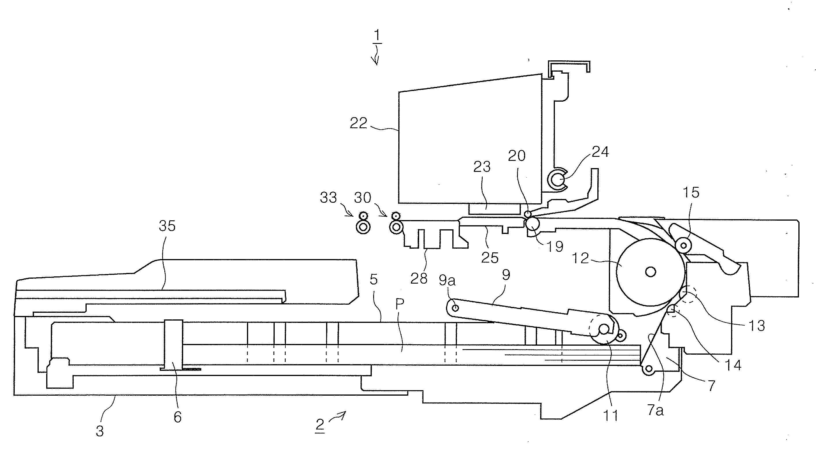
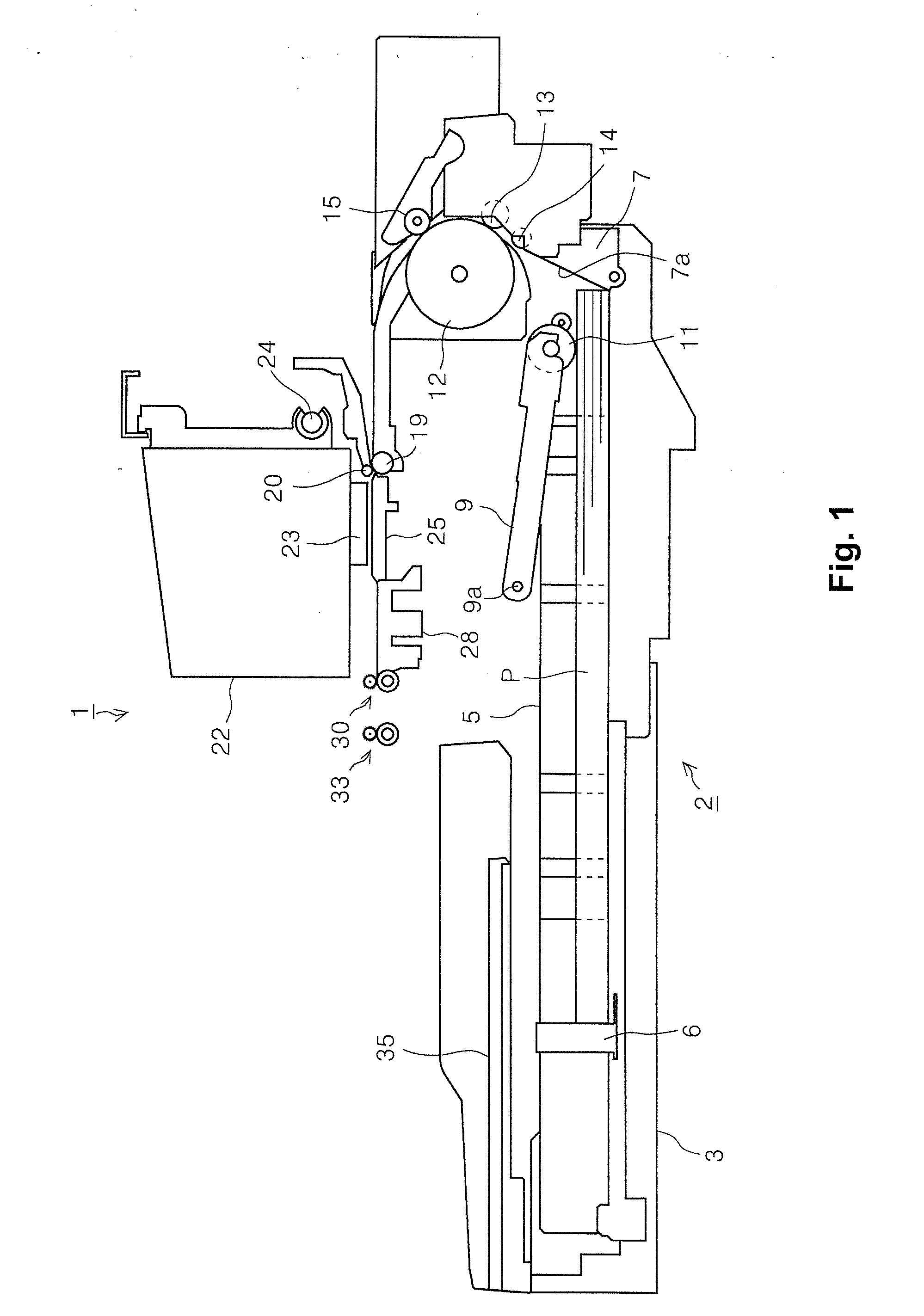
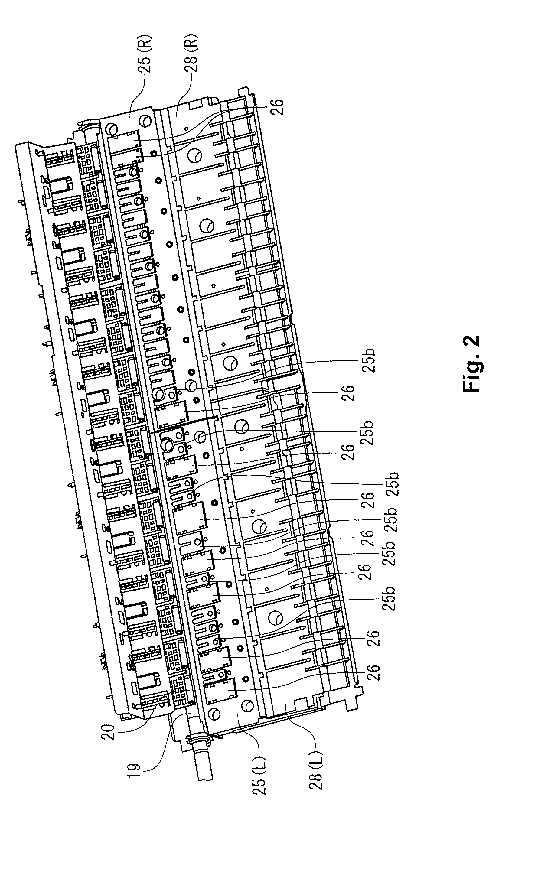
[0026]FIG. 1 is a simplified sectional side view of the paper transport path of an inkjet printer 1 described as one embodiment of the liquid ejection device or recording device according to the invention; FIG. 2 is perspective view of the vicinity of a first medium support member 25; FIG. 3 is a cutaway perspective view the first medium support member 25 (25L); and FIG. 4 is a cross-sectional view of the vicinity of a suction opening 25c in the first medium support member 25 (25L). FIG. 5 is a cross-sectional view of the vicinity of a suction opening 25c in a first medium support member 25′ according to another embodiment.

[0027]The general configuration of the inkjet printer 1 is described below. The inkjet printer 1 has a paper feeder device 2 provided in the bottom of the device. As one example of an ejection medium or recorded medium, recording paper P is fed from a paper ...


PUM


Abstract

A liquid ejection device includes a liquid ejection unit configured to eject a liquid onto an ejection medium, and an ejection medium support unit disposed on the transport path of the ejection medium and adapted to support the ejection medium. The ejection medium support unit has a suction opening for retaining the ejection medium through suctional attraction by applying suction on a back face of the ejection medium. A rim of the suction opening has a contour rising above a surrounding area of the suction opening.

Description

CROSS-REFERENCE TO RELATED APPLICATIONS[0001]This application claims priority to Japanese Patent Application No. 2010-055480 filed on Mar. 12, 2010. The entire disclosure of Japanese Patent Application No. 2010-055480 is hereby incorporated herein by reference.BACKGROUND[0002]1. Technical Field[0003]The present invention relates to a liquid ejection device for ejecting a liquid onto an ejection medium, and relates in particular to a liquid ejection device having a suction opening for retention on ejection medium supporting means adapted to support the ejection medium, through suctional attraction of the ejection medium through suction power acting on the back face of the ejection medium.[0004]2. Related Art[0005]An example of a recording device, in particular an inkjet printer, is described hereinbelow as one example of a liquid ejection device. In the field of inkjet printers, there exist inkjet printers like those disclosed in Japanese Laid-Open Patent Application 2007-98936 and J...

Claims


Application Information

Patent Timeline
IPC IPC(8): B41J2/01
CPCB41J11/0065B41J11/06B41J11/0085
Inventor OZAKI, KAZUMA
Owner SEIKO EPSON CORP
Why Eureka
Try Eureka