Bushing for a transformer

a transformer and paper bushing technology, applied in the direction of transformer/inductance details, electrical equipment, cable inlet sealing means, etc., can solve the problems of oil-impregnated paper bushings catching fire or developing oil leakage, prone to moisture ingress, and catching fire or fatalities, etc., to reduce the possibility or the extent of delamination

Active Publication Date: 2021-10-12
POWER HV INC
View PDF29 Cites 2 Cited by
  • Summary
  • Abstract
  • Description
  • Claims
  • Application Information

AI Technical Summary

Benefits of technology

[0075]The coefficient of thermal expansion of the conductor and the first layer may be selected so as to be closely aligned, thereby reduce the possibility or extent of delamination due to mechanical stress caused by a temperature gradient between the conductor and the first layer, in use.

Problems solved by technology

Existing bushings have a number of drawbacks, including:1. Oil-impregnated porcelain bushings tend to suffer from fractures, fires and / or explosions, potentially leading to injuries or fatalities.
Similarly, oil-impregnated paper bushings may catch fire or develop oil leaks, and also prone to moisture ingress.
These bushings are also dependent on the availability of oil.2. A drawback of resin bushings is that the insulation in such bushings may be relatively brittle and lack adequate resistance to shock, thus increasing the risk of failure.3. Further, bushings having insulation provided by fibreglass may be prone to delaminate due to high electric stress, moisture ingress and / or as a result of pollution.
As losses increase due to any or all the above causes, the power factor PF will also increase, reflecting deterioration in insulation ability.

Method used


Image

  • Bushing for a transformer
  • Bushing for a transformer
  • Bushing for a transformer

Examples


Embodiment Construction

[0093]The following description of the invention is provided as an enabling teaching of the invention. Those skilled in the relevant art will recognise that many changes can be made to the embodiment described, while still attaining the beneficial results of the present invention. It will also be apparent that some of the desired benefits of the present invention can be attained by selecting some of the features of the present invention without utilising other features. Accordingly, those skilled in the art will recognise that modifications and adaptations to the present invention are possible and can even be desirable in certain circumstances, and are a part of the present invention. Thus, the following description is provided as illustrative of the principles of the present invention and not a limitation thereof.

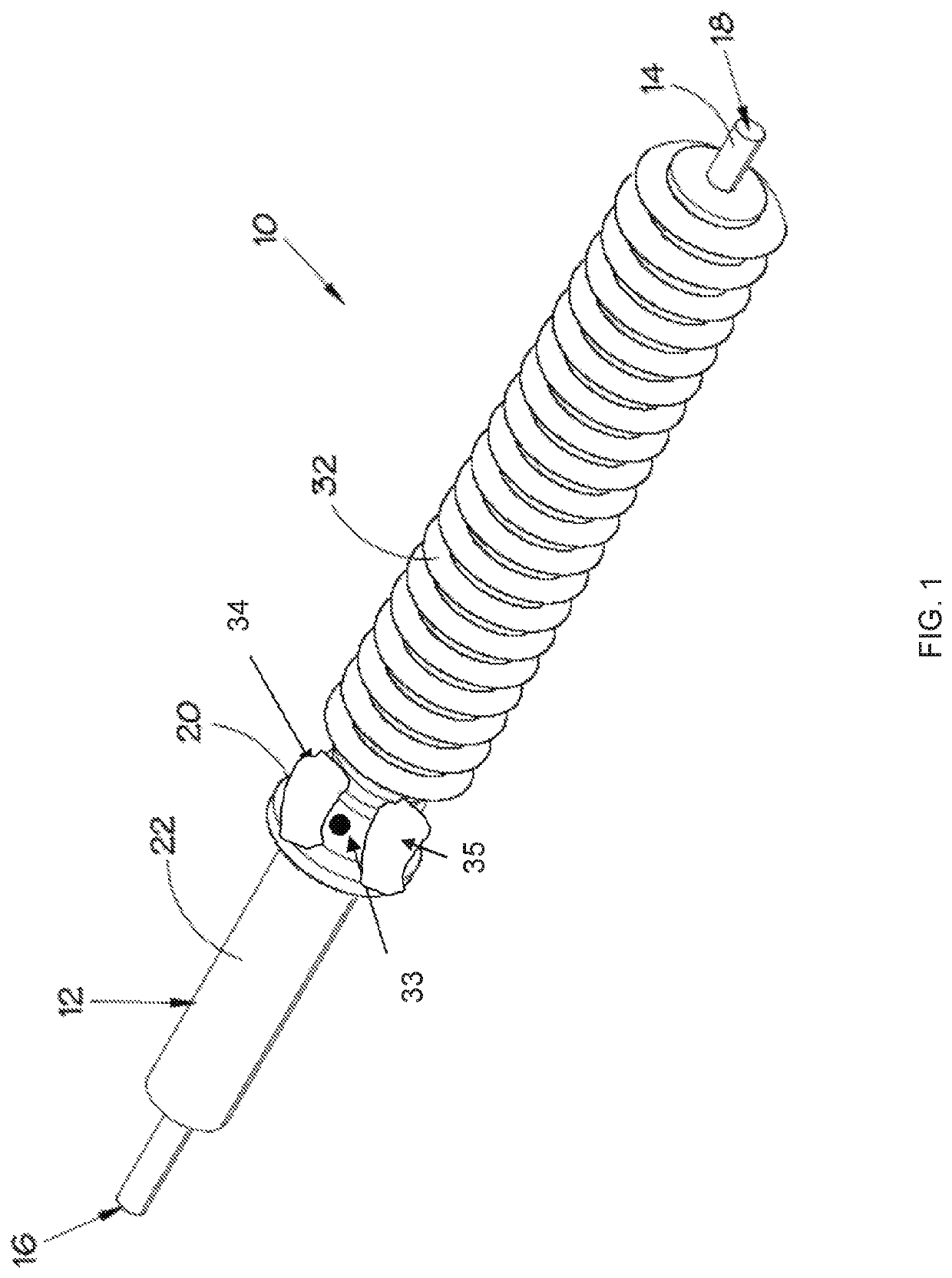
[0094]Referring to FIGS. 1 and 2, a bushing 10 for a transformer is shown, the bushing 10 comprising an elongate enclosure body 12 to accommodate a conductor 14 extending ...


PUM

PropertyMeasurementUnit
currentaaaaaaaaaa
voltagesaaaaaaaaaa
dissipation factoraaaaaaaaaa

Abstract

A bushing for a transformer is provided, the bushing comprising an elongate enclosure body to accommodate a conductor extending along a longitudinal axis, the conductor having a first terminal end a second terminal end, the ends extending from opposite sides of the enclosure body; and a mounting flange fitted to the enclosure body to enable the bushing to be mounted to an enclosure of the transformer. The enclosure body comprises two electrically insulating layers partially surrounding the conductor, a first layer of the insulating layers being substantially provided by a first polymeric material, and a second layer of the insulating layers being substantially provided by a second polymeric material, the layers being arranged about the conductor in such a manner that the bushing is substantially cavity-free. In an embodiment, the first layer defines an inner core, with the second layer providing an outer cover which at least partially covers the inner core.

Description

FIELD OF THE INVENTION[0001]The invention relates to electrical bushings. More particularly, the invention relates to an oil-free bushing, also referred to as a dry bushing, for a transformer. The invention also relates to a transformer including an oil-free bushing.BACKGROUND OF THE INVENTION[0002]When used with reference to electrical devices or systems, the term “bushing” refers to an insulated device that allows an electrical conductor to pass safely through a conducting barrier, which is usually earthed. An example of such a conducting barrier is an enclosure, or wall, of a transformer.[0003]In a power transformer, bushings serve to connect the windings of the transformer to a supply line external to the transformer, while insulating an incoming or outgoing conductor from the enclosure of the transformer.[0004]A bushing includes a conductor made of a conductive material, which connects the windings of the transformer to a supply line, and insulation partially surrounding the co...

Claims


Application Information

Patent Timeline
Patent Type & Authority Patents(United States)
IPC IPC(8): H02G15/013H01F27/04
CPCH02G15/013H01F27/04H02G15/046
Inventor DHLAMINI, SIZWE MAGIYA
Owner POWER HV INC
Why Eureka
Try Eureka