
Detecting Seismic Data in a Wellbore

a technology of seismic data and wellbore, which is applied in the field of detecting seismic data in a wellbore, can solve the problems of increasing the difficulty of lowering and raising the seismic tools hung on the cable, affecting the accuracy of seismic data, so as to achieve better acoustic coupling, high clamping pressure, and low friction

Inactive Publication Date: 2011-09-15
VCABLE
View PDF22 Cites 16 Cited by
  • Summary
  • Abstract
  • Description
  • Claims
  • Application Information

AI Technical Summary

Benefits of technology

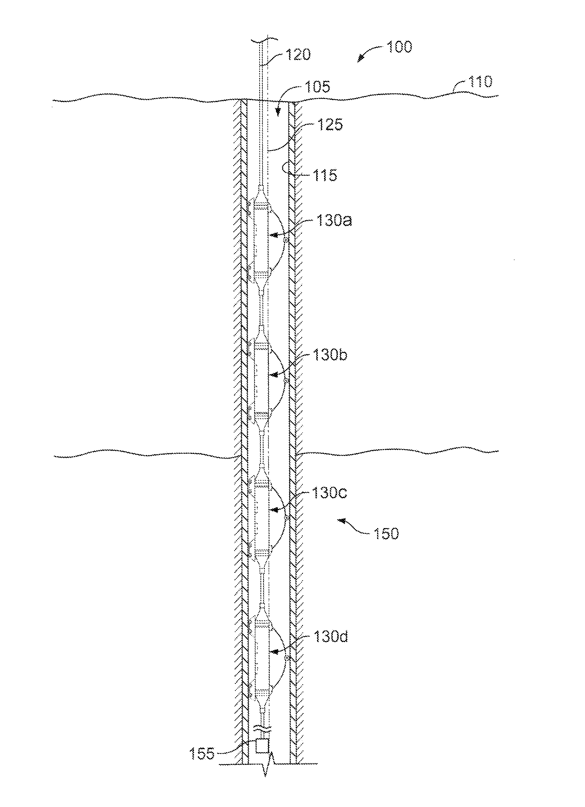
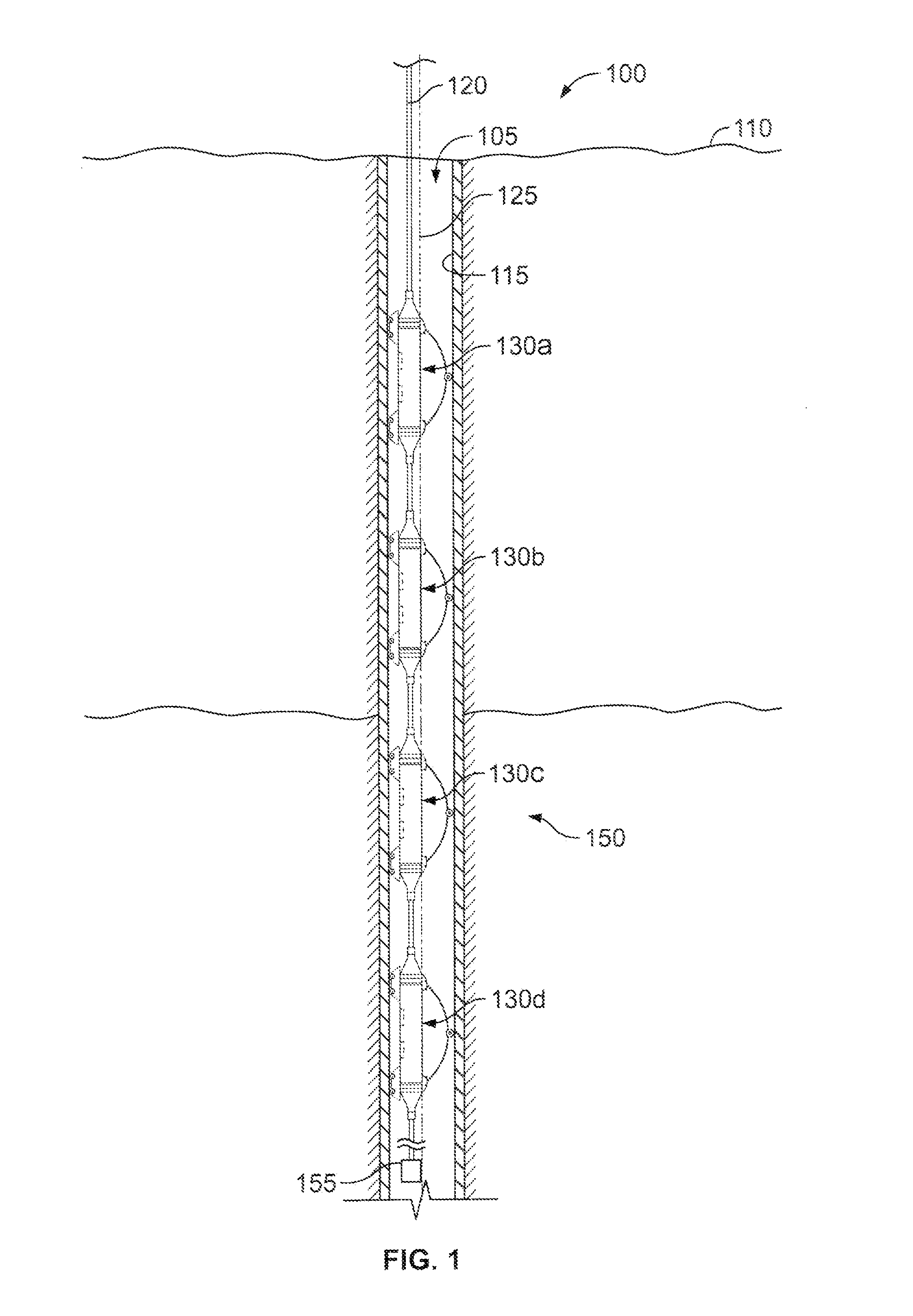
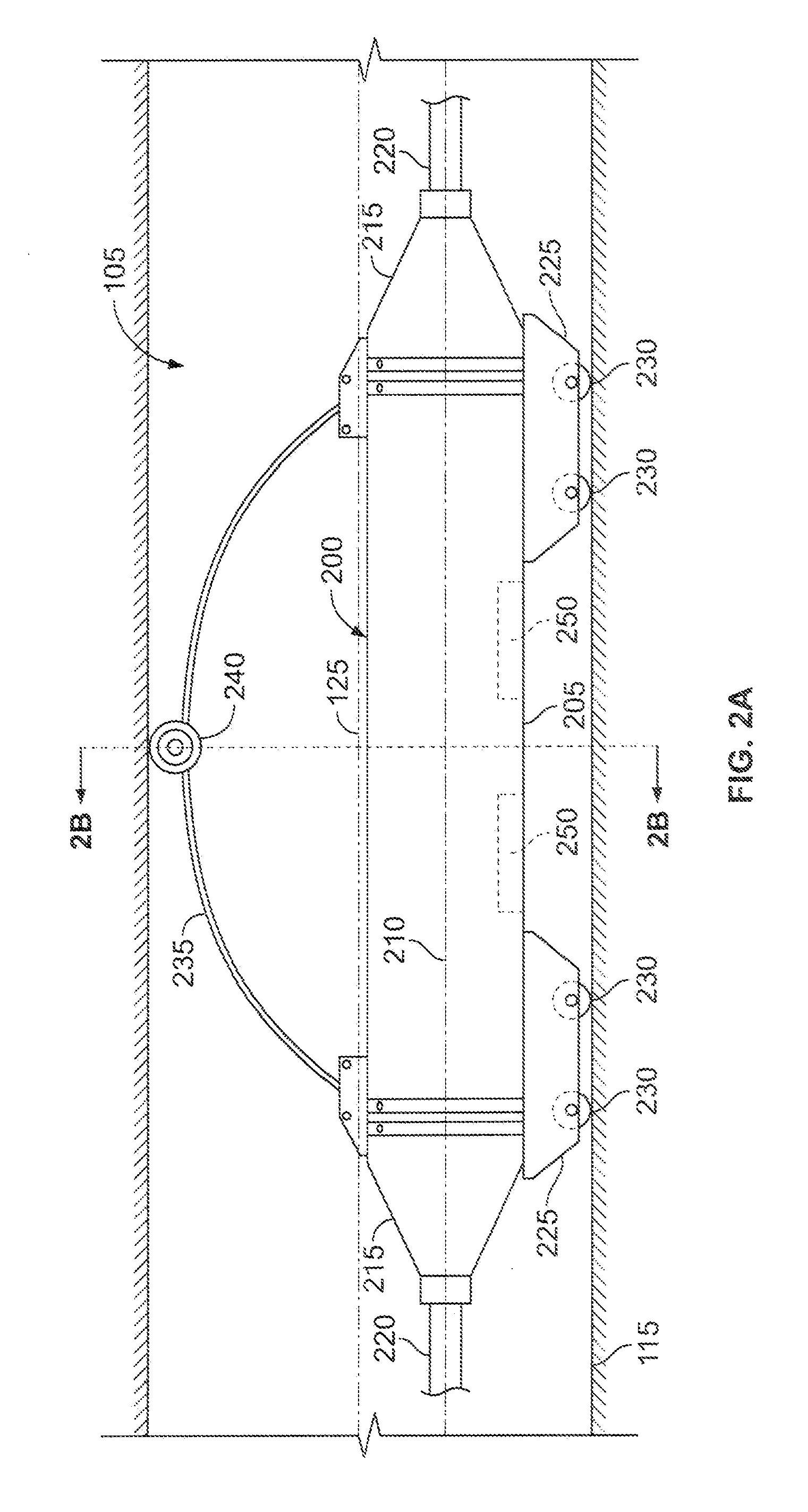
[0022]Various embodiments of a seismic tool in accordance with the present disclosure may include one or more of the following features. For example, the seismic tool may include a bow spring design that allows for high clamping pressures of the seismic tool to a borehole wall. The bow spring design may allow for better acoustic coupling of the seismic tool to a subterranean zone via the borehole wall. The seismic tool may also allow for low friction forces between the tool and the borehole wall, thereby allowing greater ease of deployment and retrieval of the seismic tool from the borehole to a terranean surface. As another example, the seismic tool may be installed in the borehole such that a longitudinal centerline of the tool is offset from a centerline of the borehole. Additionally, the seismic tool may be tailored for the application requirements and borehole diameter by adjusting a radius of the bow spring and the spring force of the bow spring. The seismic tool may also be designed for the application requirements and borehole diameter through adjustment of one or more rollers installed on the tool. As an additional example, the seismic tool may be capable of being deployed without the use of various installation and retrieval methods, such as, for example, attachment to a wireline, coiled tubing, sucker rods, or other method of forcing the seismic tool into the borehole to overcome friction created by the bow springs clamping force. For example, the seismic tool may be deployed into the borehole by utilizing a weight installed at the bottom of the cable to pull the cable, including the seismic tool, into the borehole.
[0023]Various embodiments of a seismic tool in accordance with the present disclosure may also include one or more of the following features. For example, the seismic tool may be deployed in deviated boreholes without being obstructed by a bend in the borehole. Further, the seismic tool may be configured for a specific borehole diameter or may be configured for a wide range of borehole diameters. For instance, the seismic tool may allow for a variety of bow springs with different radii to be installed on the tool to account for different borehole diameters. In addition, the seismic tool may be less complex, more reliable, and more economical than other borehole coupling methods used for seismic tools. As another example, the seismic tool may allow for a smaller and more economical cable to be utilized in deploying one or more of the tools into the borehole, because the cable may not be required to account for high clamping pressures between the tool and the borehole.

Problems solved by technology

There are several disadvantages to each of the above described methods.
For instance, the various types of lever mechanisms are usually expensive and are all subject to various types of failures.
These failures can cause the loss of data from one or more seismic tools and, in the worst case scenario, can fail to retract after actuation and result in the seismic tool becoming stuck in the borehole.
While the bow spring type devices may be designed and manufactured to provide excellent coupling, the higher the coupling force, the more difficult it may be to lower and raise the seismic tools hung on the cable.
Additionally, the more levels of seismic tools installed on the cable, the greater force required to deploy and retrieved the seismic tools, because each of the individual tools must have its own individual bow spring attached.
High clamping pressures of the bow springs to the borehole wall (e.g., those above forty to fifty pounds) may become problematic as the number of levels of seismic tools on a cable increases.

Method used


Image

  • Detecting Seismic Data in a Wellbore
  • Detecting Seismic Data in a Wellbore
  • Detecting Seismic Data in a Wellbore

Examples


Embodiment Construction

[0028]In some embodiments of a seismic tool in accordance with the present disclosure, one or more roller bearings may be secured to a housing of the tool. The tool may also include a bow spring attached to the housing and including one or more rollers (e.g., roller bearings, casters, bronzed bushings, spherical rollers, axled rollers or bearings, or other roller devices). The bow spring has a predetermined radius and spring force. As the seismic tool is deployed within a borehole, the spring force engages the rollers with a borehole wall. The seismic tool is offset with the borehole such that a longitudinal centerline of the housing is offset from a centerline of the borehole. In some embodiments, the rollers may allow for reduced friction contact between the seismic tool and the borehole wall such that repositioning and deployment of the seismic tool within the borehole may be made easier. For example, a force required to reposition and / or deploy the seismic tool may account for a...


PUM


Abstract

In one general embodiment, a seismic tool system includes a cable adapted to be deployed within a borehole; and one or more seismic tools suspendable from the cable in the borehole. At least one of the seismic tools includes at least one seismic sensor enclosed within a housing; one or more rollers attached to the housing and adapted to engage the borehole; and a bow spring attached to the housing and including one or more rollers adapted to engage the borehole. The one or more of the rollers are in acoustic communication with the seismic sensor.

Description

TECHNICAL BACKGROUND[0001]This disclosure relates to detecting seismic data in a wellbore and, more particularly, to detecting seismic data in a wellbore by one or more seismic tools lowered into a wellbore.BACKGROUND[0002]In a variety of situations, principally in oil and gas exploration, but also in environmental and civil engineering, there may be advantages to obtaining seismic data from a subterranean zone (e.g., a geological formation below the surface of the earth) by placing one or more seismic detectors in a wellbore drilled to a wide range of depths. Typically, such a seismic detector, often called a “sonde” or alternatively a “seismic tool,” is suspended from a cable and lowered into a borehole to a depth determined to be appropriate for the acquisition of seismic data relevant to the target area (i.e., the subterranean zone).[0003]The seismic tools may be either digital or analog in design. Typically, a digital tool will include an analog to digital converter for the sei...

Claims


Application Information

Patent Timeline
Patent Type & Authority Applications(United States)
IPC IPC(8): G01V1/40
CPCG01V1/52
Inventor FUSSELL, DON L.
Owner VCABLE
Learn More