
Boom with ramped or horizontal skirt structure for slowing the flow speed of buoyant fluids on moving water for fluid, containment, fluid containment system and method

a boom and flow speed technology, applied in water cleaning, hydraulic engineering, construction, etc., can solve the problems that prior booms have never succeeded in containing floating fluids on moving water, and achieve the effect of slowing the speed of fluid

Inactive Publication Date: 2006-06-06
WONG KAU FUI VINCENT +1
View PDF15 Cites 15 Cited by
  • Summary
  • Abstract
  • Description
  • Claims
  • Application Information

AI Technical Summary

Benefits of technology

[0021]The flow slowing boom preferably additionally includes at least one tow cord secured to the support structure for engagement by water vessels for use in pulling the flow slowing boom through the water, for greater ease of deployment and retrieval of the flow slowing boom and for moving the flow slowing boom to new positions and to different containment sites.
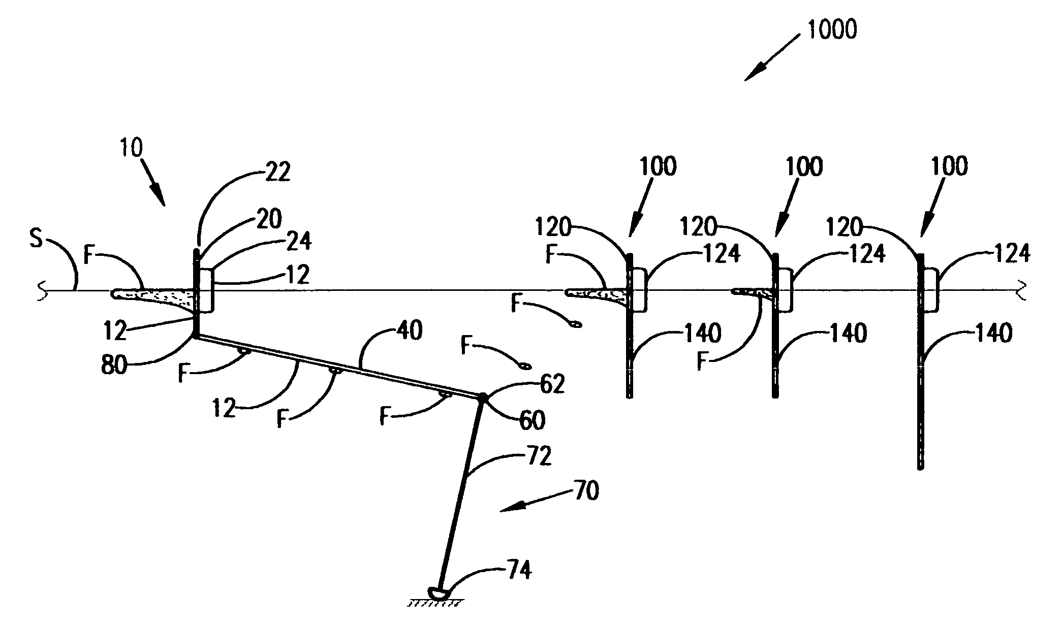
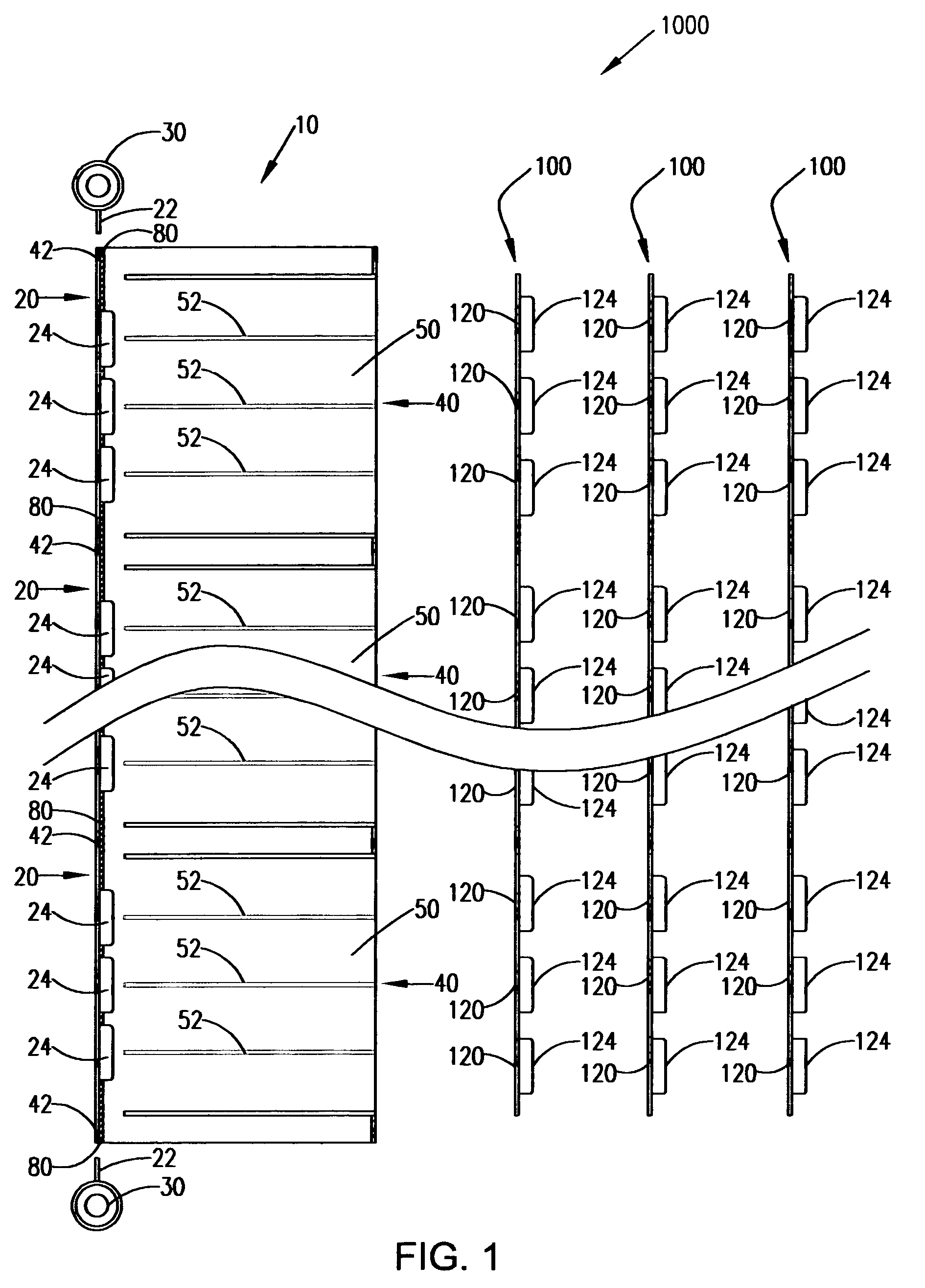
[0022]A flow slowing boom for slowing the speed of a buoyant fluid floating on moving water having a direction of water movement and a water surface, the flow slowing boom including a support structure for positioning at the surface of a body of water across the direction of water movement; an anchoring structure for anchoring the support structure relative to the moving water; a skirt structure connected to the support structure such that the skirt structure is positioned out of a vertical orientation to an angle in a range of beyond vertical including horizontal, thereby constraining buoyant fluid to flow across the skirt structure to slow the speed of the fluid and thus to permit the fluid to buoy toward the water surface for containment.
[0023]The flow slowing boom preferably additionally includes at least one tow cord secured to the support structure for engagement by water vessels for use in pulling the flow slowing boom through the water, for greater ease of deployment and retrieval of the flow slowing boom and for moving the flow slowing boom to new positions and to different containment sites.
[0024]A flow slowing boom is further provided for slowing the speed of a buoyant fluid floating on moving water having a direction of water movement and a water surface, the flow slowing boom including a support structure for positioning at the surface of a body of water across the direction of water movement; an anchoring structure for anchoring the support structure relative to the moving water; a stiff skirt structure connected to the support structure so that the skirt structure is positioned out of a vertical orientation to an angle in a range of beyond vertical including horizontal, thereby constraining buoyant fluid to flow across the skirt structure to slow the speed of the fluid and thus to permit the fluid to buoy toward the water surface for containment.
[0025]A flow slowing boom is still further provided for slowing the speed of a buoyant fluid floating on moving water having a direction of water movement and a water surface, the flow slowing boom including a support structure for positioning at the surface of a body of water across the direction of water movement; an anchoring structure for anchoring the support structure relative to the moving water; a buoyant skirt structure which is one of planar and convex having a convex first broad face and a second broad face and for floating on the body of water with the first broad face directed downwardly so that the average position of the skirt structure is horizontal, thereby constraining buoyant fluid to flow across the skirt structure to slow the speed of the fluid and thus to permit the fluid to buoy toward the water surface for containment.

Problems solved by technology

These prior booms have always not been successful in containing floating fluids on moving water, and especially where the movement is rapid.

Method used


Image

  • Boom with ramped or horizontal skirt structure for slowing the flow speed of buoyant fluids on moving water for fluid, containment, fluid containment system and method
  • Boom with ramped or horizontal skirt structure for slowing the flow speed of buoyant fluids on moving water for fluid, containment, fluid containment system and method
  • Boom with ramped or horizontal skirt structure for slowing the flow speed of buoyant fluids on moving water for fluid, containment, fluid containment system and method

Examples


first preferred embodiment

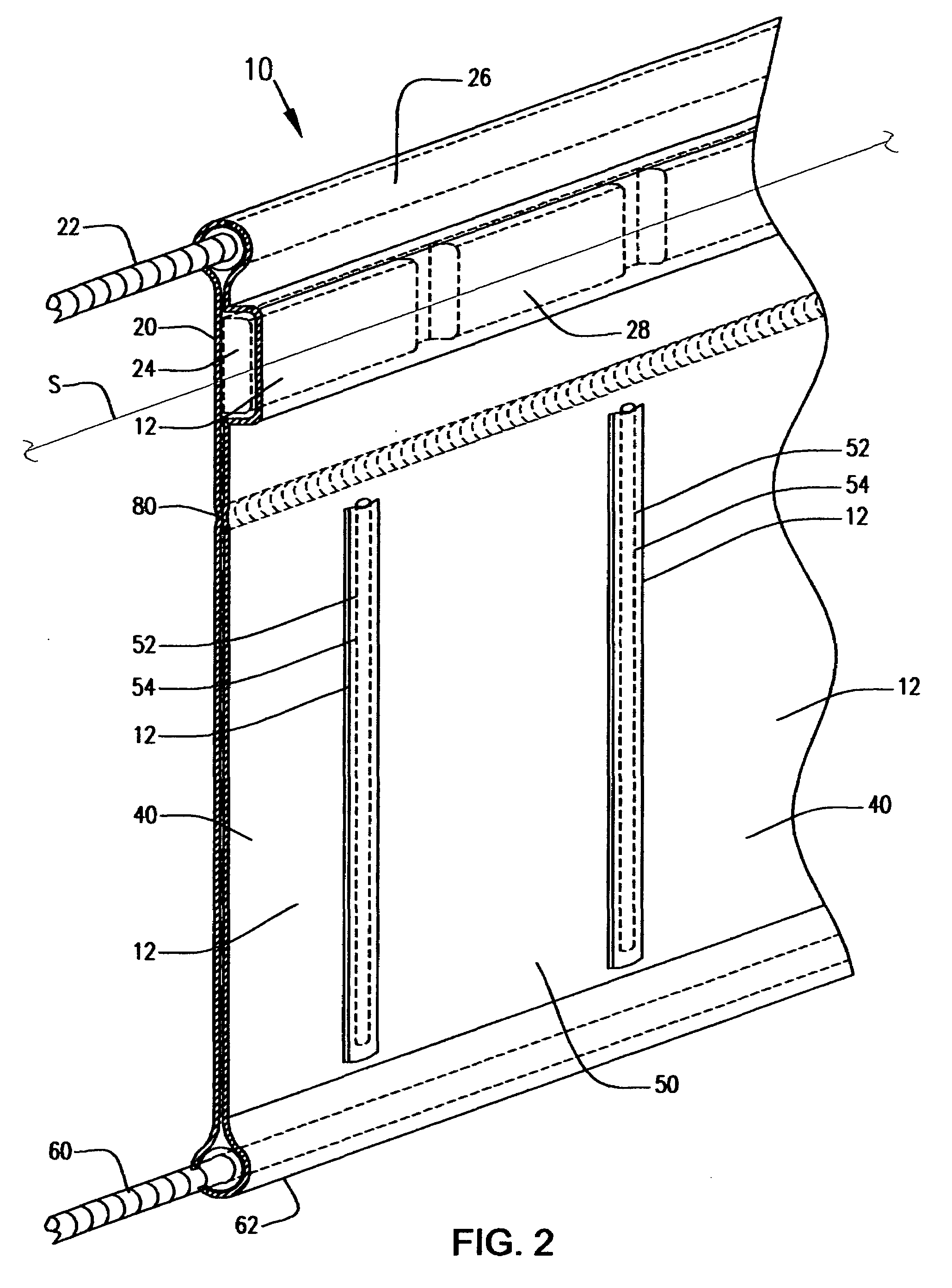
[0038]Referring to FIGS. 1–6, a flow slowing boom 10 is disclosed including a support structure 20 for anchoring in a body of moving water and positioning at the water surface S across the direction of water flow so that the support structure 20 protrudes above the water surface S and thereby prevents the fluid F from flowing over the top of flow slowing boom 10, and a rigid or stiff skirt structure 40 which preferably is either planar or convex in cross-sectional shape against the direction of water movement pivotably suspended from the support structure 20 with pivot means 80 so that water movement pivots the skirt structure 40 out of a vertical orientation to an average position at any of a range of angles between 30 degrees and 95 degrees from vertical in the direction of water flow, and preferably at an angle from vertical between 75 and 92 degrees in the direction of water flow, thereby constraining a buoyant target fluid F floating at and near the water surface S to flow acro...

second preferred embodiment

[0048]For a second embodiment of the flow slowing boom, the skirt structure 40 itself is buoyant and floats on the moving water with an average position which is horizontal. Skirt structure 40 preferably is flexible, but may be stiff. As a result, buoyant fluid F is constrained to flow across the skirt structure to slow the speed of the fluid F and thus to permit the fluid F to buoy toward the water surface S for containment.

Method

[0049]In practicing the invention, the following method may be used. A method is also provided of containing fluid floating on a body of moving water including the steps of providing a flow slowing boom 10 having a support structure 20 and a stiff skirt structure 40 pivotally suspended from the support structure 20, positioning the support structure 20 along the surface S of the body of water across the direction of water flow so that the skirt structure extends downwardly from the support structure, providing an anchoring structure; securing the support s...


PUM


Abstract

A flow slowing boom for slowing the speed of a buoyant fluid floating on moving water having a direction of water movement and a water surface includes a support structure for positioning at the surface of a body of water across the direction of water movement; an anchoring structure for anchoring the support structure relative to the moving water; a skirt structure; and a pivot structure interconnecting the support structure and the skirt structure so that the skirt structure is pivotably suspended from the support structure and moving water pivots the skirt structure out of a suspended vertical orientation to any of a range of angles beyond vertical including horizontal, thereby constraining buoyant fluid to flow across the skirt structure to slow the speed of the fluid and thus to permit the fluid to buoy toward the water surface for containment. A boom system and method are also provided.

Description

FILING HISTORY[0001]This application is related to disclosure document No. 559499 filed on Aug. 24, 2004.BACKGROUND OF THE INVENTION[0002]1. Field of the Invention[0003]The present invention relates generally to the field of devices and systems for containing environmentally hazardous buoyant fluids spilled on water such as oil. More specifically the present invention relates to a flow slowing boom including a ramped or horizontal skirt structure for placement at the surface of a body of moving water across the direction of flow for slowing the speed of buoyant fluids in the water to permit the fluids to buoy toward the water surface for containment. The flow slowing boom preferably includes a support structure for deployment at the water surface and connected to a boom anchoring structure for maintaining the position of the support structure, and a skirt structure pivotably suspended from the support structure with pivot means so that water movement pivots the skirt structure out o...

Claims


Application Information

Patent Timeline
Patent Type & Authority Patents(United States)
IPC IPC(8): E02B15/04
CPCE02B15/08E02B15/0842E02B15/0814E02B15/0807
Inventor WONG, KAU-FUI VINCENTMILLER, MICHAEL K.
Owner WONG KAU FUI VINCENT
Learn More