Device for measuring foamed media

Active Publication Date: 2011-09-22
HELLA KG HUECK & CO
View PDF5 Cites 9 Cited by
  • Summary
  • Abstract
  • Description
  • Claims
  • Application Information

AI Technical Summary

Benefits of technology

[0008]The object of the invention is to provide a device of the kind mentioned at the outset in which the pre-volume is designed in such a

Problems solved by technology

The fluid is here intensively swirled, especially during the transition from one to th

Method used


Image

  • Device for measuring foamed media
  • Device for measuring foamed media
  • Device for measuring foamed media

Examples


Embodiment Construction

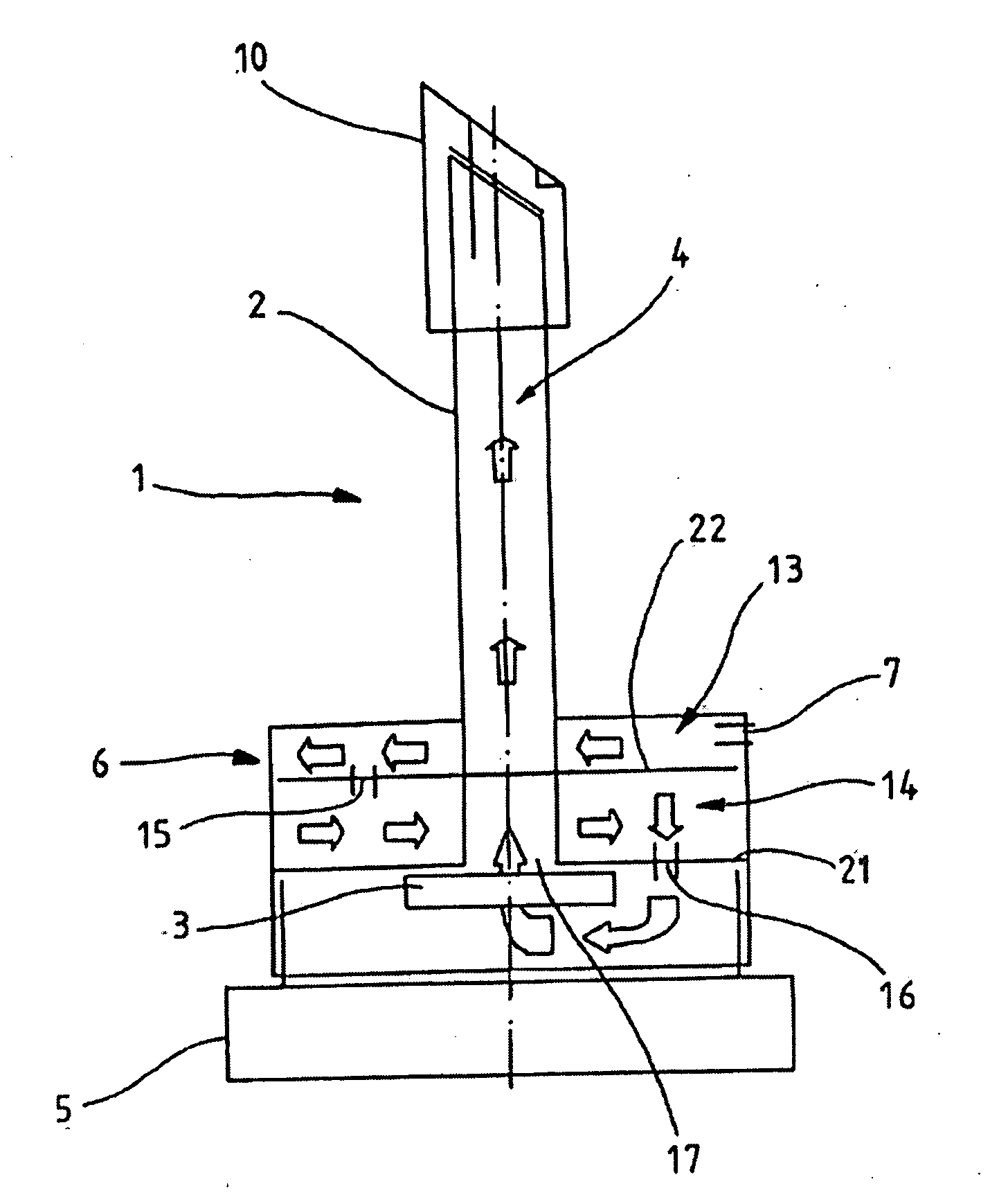
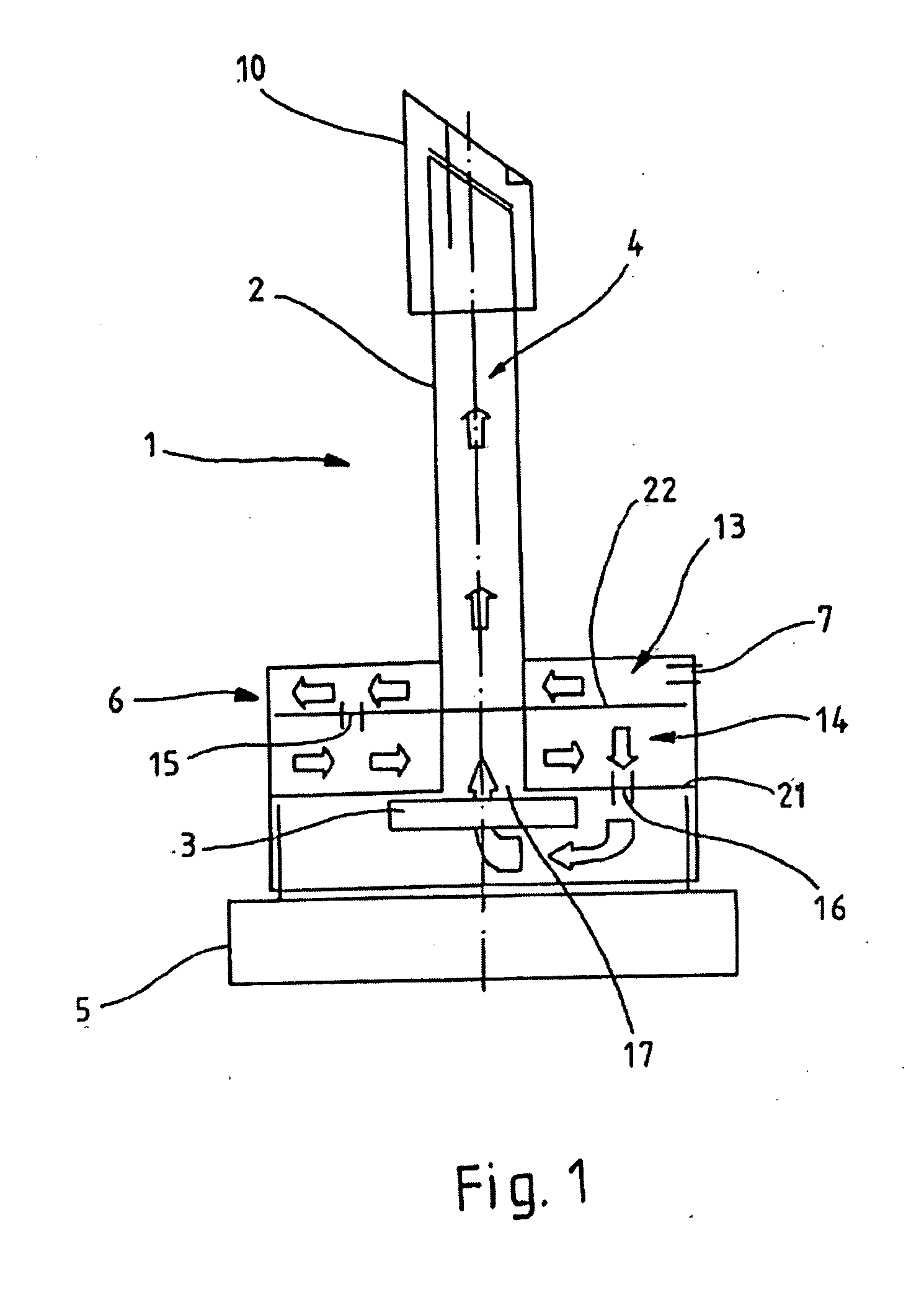
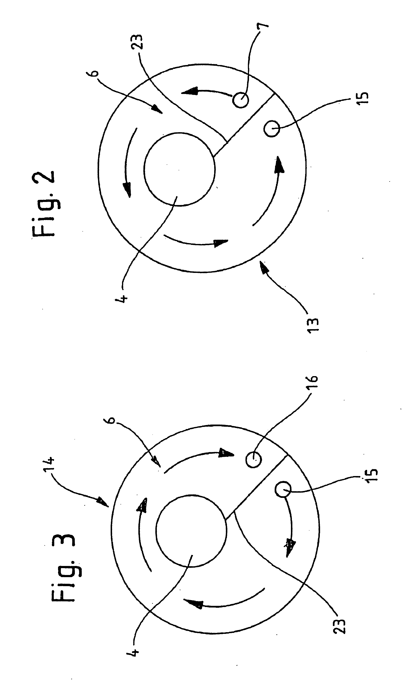
[0035]An antechamber 6 of a device 1 for determining the fill level in a container has an upper and lower plane 13, 14, wherein a flow passes through both planes 13, 14 in opposing directions. FIG. 1 to FIG. 3 show the direction of flow of an inflowing fluid in the device 1. The floor area of the device 1 on FIG. 1 has an ultrasound sensor 3. This ultrasound sensor 3 is arranged on a pedestal element 5 of the device 1. A damping beaker 2 is arranged centrally over the ultrasound sensor 3, wherein the interior of the damping beaker 2 has a measuring section 4. Given a filled container, this measuring section 4 is occupied with fluid, in particular oil, in an oil pan of a motor vehicle, depending on the fill level of the container.

[0036]The ultrasound sensor 3 and measuring section 4 are arranged one over the other along a line, wherein the ultrasound sensor 3 sends the generated sound waves into the measuring section 4 of the damping beaker 2. To obtain correct measured values, the u...


PUM


Abstract

A device for measuring the fill level in a container has an ultrasound sensor and a damping beaker with at least one antechamber. The antechamber has an inlet opening to the container and an outlet opening to the damping beaker, and has a geometric structure, which guides a fluid at least once around the midpoint of the damping beaker. The antechamber has at least two planes lying horizontally over each other. Each plane has a geometric structure, and the geometric structures of the planes are designed so that the fluid streams through the planes in opposite directions. As a result, the path to be traversed in the antechamber is lengthened, and the inflowing medium is additionally swirled. Even foamed media that quickly flow into the antechamber are effectively retained, and degassing is possible prior to entry into the measuring section of the ultrasound sensor.

Description

CROSS REFERENCE TO RELATED APPLICATIONS[0001]Applicants claim priority under 35 U.S.C. 119 of German Application No. 10 2010 011 490.1 filed Mar. 16, 2010, the disclosure of which is incorporated by reference.BACKGROUND OF THE INVENTION[0002]The invention relates to a device for measuring a fill level in a container with an ultrasound sensor, wherein the ultrasound sensor has allocated to it a damping beaker with at least one antechamber, and the antechamber has an inlet opening to the container and an outlet opening to the damping beaker.[0003]Predominantly ultrasound sensors are used to determine the oil level in engines. These emit sound waves, which are reflected at the interface between two media, e.g., gas and oil, wherein fluids other than oil can also be measured, and again received by the ultrasound sensor. The fill level in the container having the device can then be derived from the determined runtime of the sound waves. However, the fill level is difficult if not impossi...

Claims


Application Information

Patent Timeline
IPC IPC(8): F01M1/02G01F23/296
CPCG01F23/296F01M11/12
Inventor NIEMANN, THOMASKUECK, THOMASZOYKE, INGOHESSENKAEMPER, DAVIDTONEWIZKI, SERGEJ
Owner HELLA KG HUECK & CO
Why Eureka
Try Eureka