Method for measuring liquid level in single crystal pulling apparatus employing cz method

a single crystal pulling and liquid level technology, applied in the direction of polycrystalline material growth, crystal growth process, protective fluid, etc., can solve the problems of weak intensity of laser beam ultimately received by the photodetector, return reflection method, and stable detection of hammer beam, so as to achieve reliably and stably measured melt level, reliable and easy measurement

Active Publication Date: 2011-05-19
SUMCO TECHXIV
View PDF5 Cites 6 Cited by
  • Summary
  • Abstract
  • Description
  • Claims
  • Application Information

AI Technical Summary

Benefits of technology

[0049]According to the first aspect of the present invention, an optimal reflection method can be selected even if the gap D1, i.e. the gap D varies widely. As a result, the melt level can be measured reliably and stably.
[0050]According to the second aspect of the present invention, an optimal reflection method can be selected on the basis of a gap D actually measured. As a result, the melt level can be measured reliably and easily using the optimal reflection method.
[0051]According to the t

Problems solved by technology

The inclination of the melt surface shifts the angle of the reflection beam of the laser beam, and hampers stable detection of the beam.
The direct reflection method has a drawback in that the gap D decreases when there is set a large diameter of the pulled single crystal, and in consequence, the laser beam is reflected on a large-inclination spot.
On the other ha

Method used


Image

  • Method for measuring liquid level in single crystal pulling apparatus employing cz method
  • Method for measuring liquid level in single crystal pulling apparatus employing cz method
  • Method for measuring liquid level in single crystal pulling apparatus employing cz method

Examples


embodiment 1

[0120]In Embodiment 1, a specific reflection path is selected from among three reflection paths on the basis of one parameter, namely a gap D1.

[0121]FIG. 5 is a diagram illustrating reflection paths of three reflection methods as well as the arrangement of a single crystal having three outer diameters.

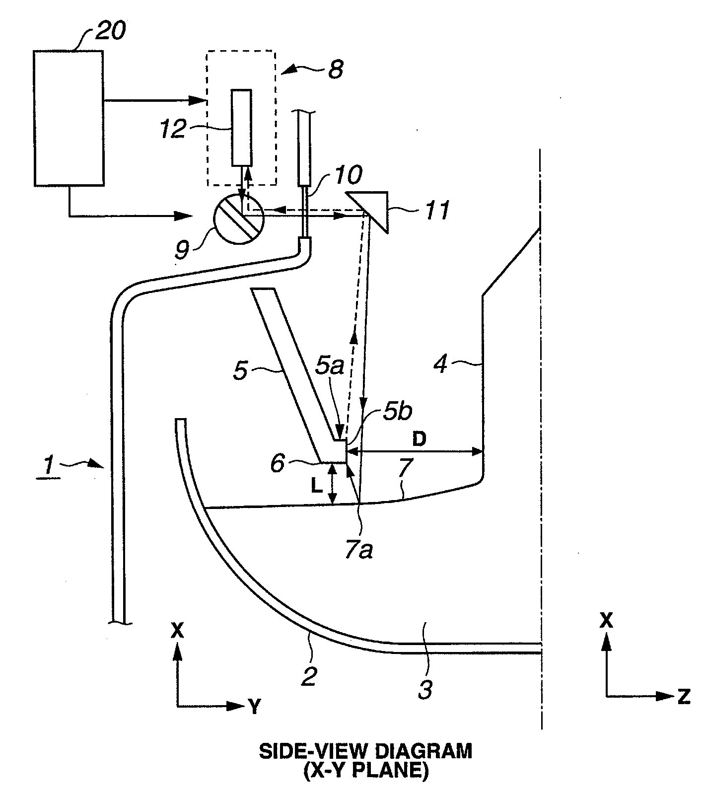
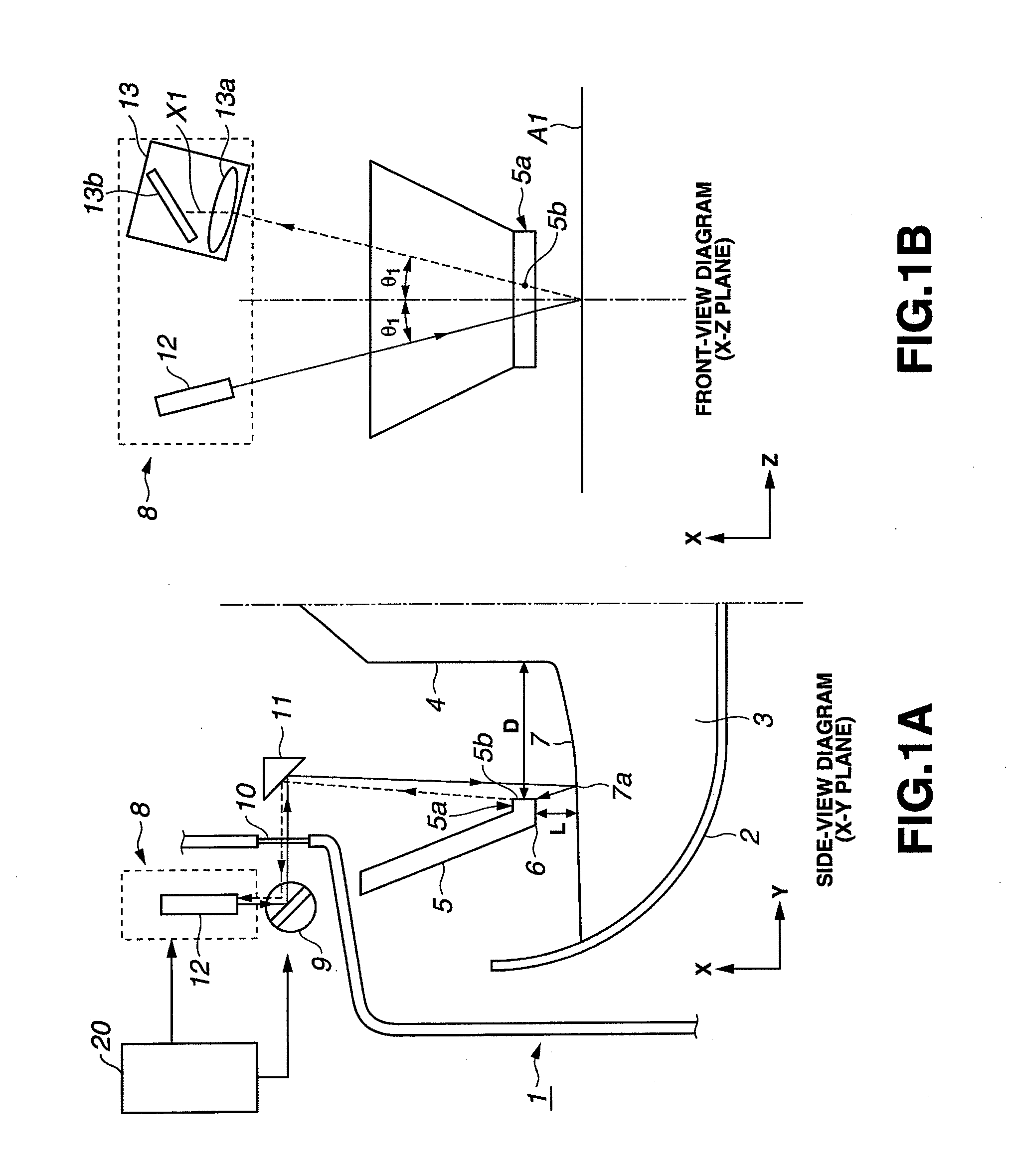
[0122]In FIG. 5, the reference numeral D1 denotes the gap between the outer periphery of a single crystal and a predetermined position defined by a perpendicular line L1 drawn from an end of the prism 11. The figure depicts a single crystal having three outer diameters for which the gap D1 is 10 mm, 15 mm and 23 mm.

[0123]The reference numeral D2 denotes the gap between the side face 5b of the rim 5a of the heat shield 5 and a predetermined position defined by a perpendicular line L1 drawn from an end of the prism 11. The gap D2 is determined by the construction of the CZ furnace. The gap D is the sum of the gap D1 and the gap D2, and hence the gap D1 can be easily worked out as D1=D−D2...

embodiment 2

[0143]In Embodiment 1, a reflection path was selected from among three reflection paths on the basis of one parameter, namely the gap D1. However, two or more parameters may be used for selecting a specific reflection method.

[0144]A relationship between the gap L and beam reception probability will be explained first for the three reflection methods. The gap L is the distance between the lower face 6 of the rim 5a of the heat shield 5 and the melt surface 7.

[0145]FIG. 8 is a diagram illustrating a comparison of reflection paths within the CZ furnace, in the X-Y plane, for the three reflection methods. FIG. 8A illustrates a reflection path for the direct reflection method, FIG. 8B illustrates a reflection path for the return reflection method, and FIG. 8C illustrates a reflection path for the side-face reflection method.

[0146]As shown in FIG. 8A, in the direct reflection method, a laser beam emitted by a range-finding unit, not shown, and entering into the CZ furnace from the left of...

embodiment 3

[0168]In Embodiment 1 and Embodiment 2, a specific reflection method is selected from among three reflection methods on the basis of predetermined parameters.

[0169]In Embodiment 3, the actual gap D and gap L are measured, during pulling of the single crystal, by a measuring means provided in the CZ furnace. A specific reflection method is then selected from among three reflection methods on the basis of measurement values.

[0170]An explanation follows first on a method for measuring the gap D and the gap L, and then on a measuring method that is based on the measurement values.

(1) Measurement of the Gap D

[0171]For instance, the method for measuring the gap D as disclosed in Patent document 1 can be used here as the method for measuring the gap D.

[0172]FIGS. 12 and 13 are diagrams for explaining a method for measuring the gap D. FIG. 13 is a cross-sectional diagram of the CZ furnace of FIG. 12 along a plane A-A.

[0173]The silicon raw material 3 is melted inside the crucible 2 in the CZ...


PUM


Abstract

Provided is a method for reliably and easily measuring a liquid level by selecting an optimal reflection method from among a plurality of reflection methods, depending on growing conditions of a pulled single crystal. The method comprises: setting a plurality of measuring methods having different ways of determining the liquid level; creating, in advance, information that associates with a gap between the outer peripheral face of the single crystal and a predetermined position located between a heat shield and the outer peripheral face of the single crystal; determining the gap in accordance with manufacturing conditions; selecting a measuring method associated to the determined gap, on the basis of the information; and measuring the liquid level of a melt surface in use of the selected measuring method.

Description

TECHNICAL FIELD[0001]The present invention relates to a position measuring method based on the principle of triangulation, and more particularly, to a method for measuring liquid level in a raw material melt liquid in a single crystal pulling apparatus employing a Czochralski method.BACKGROUND ART[0002]The Czochralski method (CZ method) involves pulling up a growing single crystal ingot from a raw material melt, for instance of silicon, in a crucible. In order to appropriately control the growth of the single crystal, the liquid level (hereafter, melt level) of the raw material melt must be accurately measured, and the position thereof must be adjusted according to the growth of the single crystal.[0003]In particular, silicon single crystal pulling apparatuses (CZ furnaces) using the CZ method are ordinarily provided with a heat shield for controlling the heat radiation from a heater and the silicon melt, and for straightening the flow of gas infused into the CZ furnace.[0004]The th...

Claims


Application Information

Patent Timeline
IPC IPC(8): C30B15/20C30B15/16
CPCC30B15/14C30B15/26C30B29/06Y10T117/1008Y10T117/1068Y10T117/1012Y10T117/1032Y10T117/1072Y10T117/1024Y10T117/10Y10T117/1004
Inventor HAYASHIDA, TOSHIOKIHARA, AYUMITAKAMI, TAKUAKI
Owner SUMCO TECHXIV
Why Eureka
Try Eureka