

Adapter for multifunctional tool
a multi-functional tool and adapter technology, applied in the field of multi-functional tools, can solve the problems of limited universality and inability to meet the demands of users
- Summary
- Abstract
- Description
- Claims
- Application Information
AI Technical Summary
Problems solved by technology
Method used
Image

Examples
second embodiment
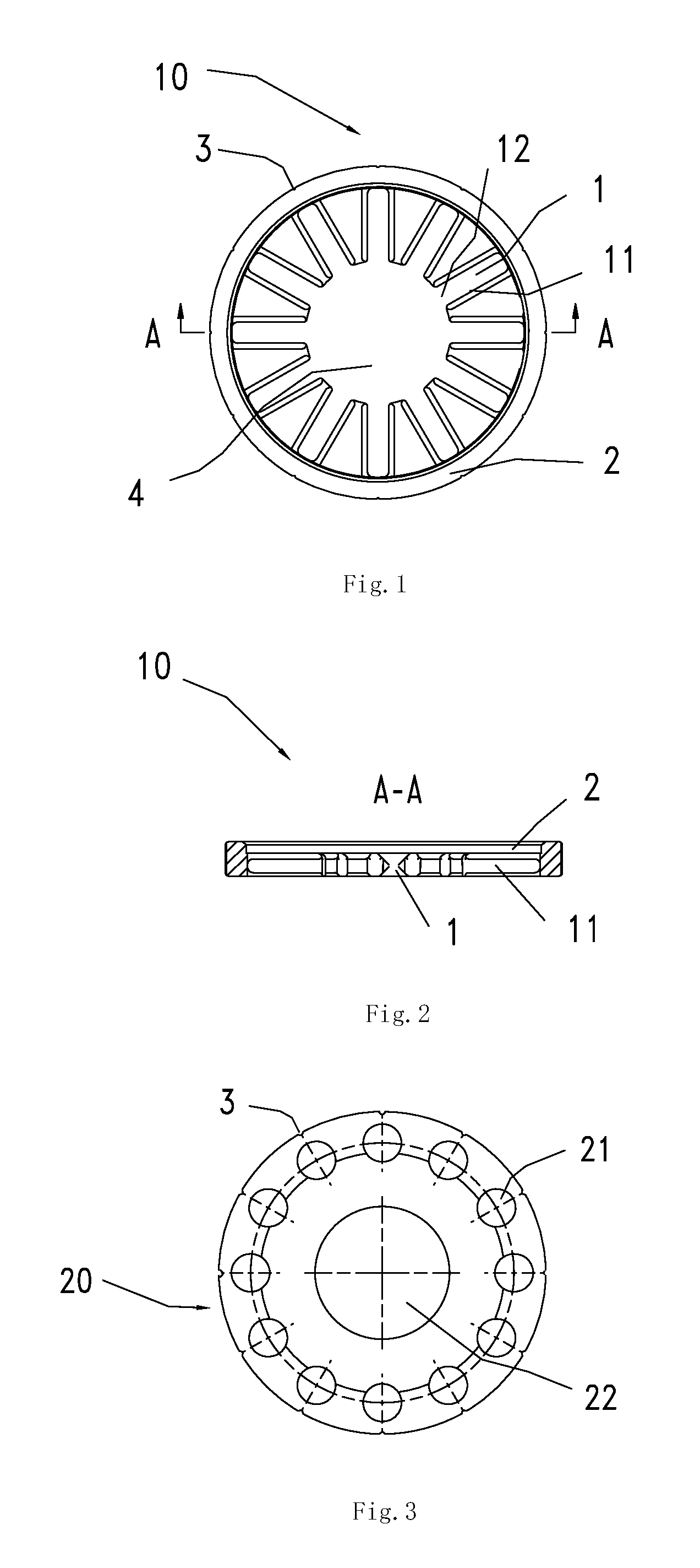
Referring to FIG. 7, a converter 10 of a further adapter for a multifunctional tool is shown. The converter 10 of the second embodiment is disc-shaped as a whole with a first form-locating component 1 and a second form-locating component 5 arranged thereon. The second form-locating component 5 is a polygonal shaped hole located at center of the converter 10, and the first form-locating component 1 is embodied as a plurality of the grooves radially extending on the outer surface of the polygonal shaped hole along the circumferential direction. The radially extending grooves are arranged on one end side of the disc-shaped converter 10.
first embodiment
The fixer 20 of the adapter for the multifunctional tool is the same as that of the
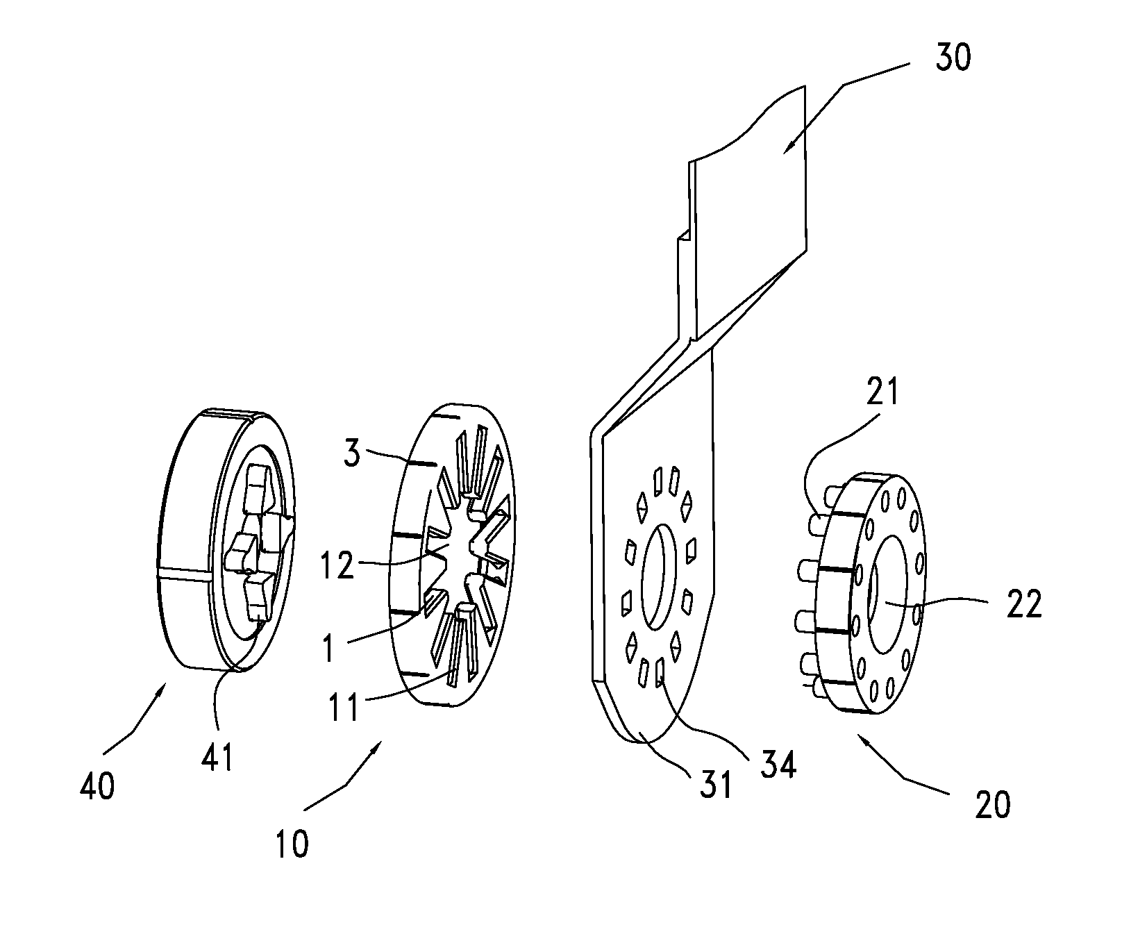
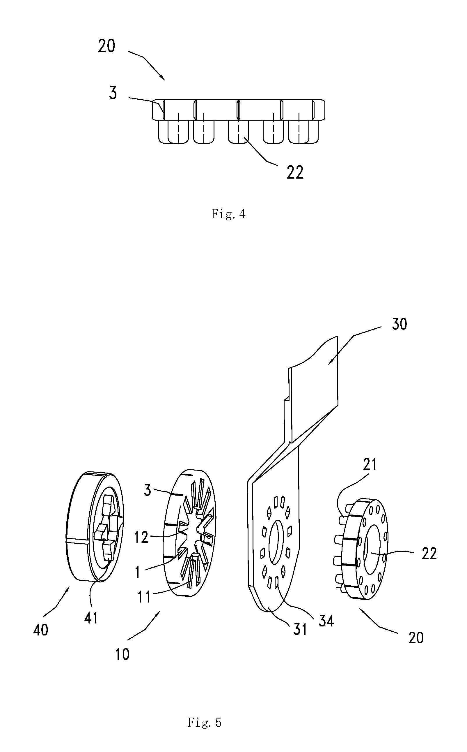
As shown in FIG. 8, the shaft end 40 of the output shaft of the multifunctional tool is mounted with a tool head 30 with the aid of the adapter of the second embodiment. A form-fit component 21 on the fixer 20 passes through the hole 34 of the connecting segment 31 of the tool head 30 and is mated with the second form-locating component 5 on the converter 10. Because the second form-locating component 5 is a polygonal shaped hole, the fixer cannot be rotated along the circumferential direction relative to the converter 10 to achieve the circumferential locating. The axial protrusions 41 arranged on the shaft end 40 are embedded into the first form-locating component 1 of the converter 10.
Referring to FIG. 9, the first form-locating component 1 and the second form-locating component of the adapter could be exchanged with each other. For example, the first form locating component 1 arranged as radial gr...
PUM
 Abstract
Description
Claims
Application Information