Lighting device

a technology of lighting devices and light beams, which is applied in the direction of fixed installation, lighting and heating equipment, instruments, etc., can solve the problems of limited disposition conditions, difficult to illuminate a road surface near the road shoulder between the lighting devices, and large depth in the deeper direction, so as to reduce the glare, prevent glare light, and widen the horizontal illumination area

Inactive Publication Date: 2011-09-29
STANLEY ELECTRIC CO LTD
View PDF4 Cites 6 Cited by
  • Summary
  • Abstract
  • Description
  • Claims
  • Application Information

AI Technical Summary

Benefits of technology

The presently disclosed subject matter was devised in view of these and other problems and features and in association with the conventional art. According to an aspect of the presently disclosed subject matter, a lighting device can be configured to have a depth dimension that is smaller than a conventional lighting device, and to provide a desired light distribution pattern without any adjustment of the angular postures of a plurality of components such as reflecting minors, projection lenses, and the like while the lighting device can prevent glare light from occurring (i.e, suppressing glare) toward a driver of an oncoming vehicle even if the lighting device is disposed at a lower position, for example, 1 m high from a road surface. According to another aspect of the presently disclosed subject matter, a lighting device can illuminate a road surface including areas near the road shoulder between adjacent lighting devices with light even if the lighting devices are disposed at certain intervals along the road shoulder. Accordingly, it is possible to improve the illumination uniformity (uniformity ratio of illuminance) in the illumination area.
As described above and according to an exemplary embodiment, first the lighting device can be configured to have a depth dimension smaller than a conventional lighting device. Secondly, the lighting device can be configured to provide a desired light distribution pattern without any adjustment of angular postures of a plurality of components such as reflecting minors, projection lenses, and the like. Thirdly, the lighting device can prevent glare light from occurring (i.e., can suppress glare) toward the driver of an oncoming vehicle even if the lighting device is disposed at a lower position, for example, 1 m high from a road surface. Furthermore, the lighting device can illuminate a road surface including areas near its road shoulder between adjacent lighting devices with light even if the lighting devices are disposed at certain intervals along the road shoulder. Accordingly, it is possible to improve the illumination uniformity (uniformity ratio of illuminance) in the illumination area.

Problems solved by technology

The lighting device 400 with the above configuration, however, has problems in which its size in the deeper direction (depth) may be large due to its configuration and the disposition conditions therefore may be limited.
Furthermore, if the lighting devices 400 with the above configuration are disposed at certain intervals as shown in FIGS. 2A and 2B, it may be difficult to illuminate a road surface near the road shoulder between the lighting devices 400.
Accordingly, it is difficult to improve the illumination uniformity (uniformity ratio of illuminance) in the illumination area.

Method used


Image

  • Lighting device
  • Lighting device
  • Lighting device

Examples


Embodiment Construction

A description will now be made below to lighting devices of the presently disclosed subject matter with reference to the accompanying drawings in accordance with exemplary embodiments.

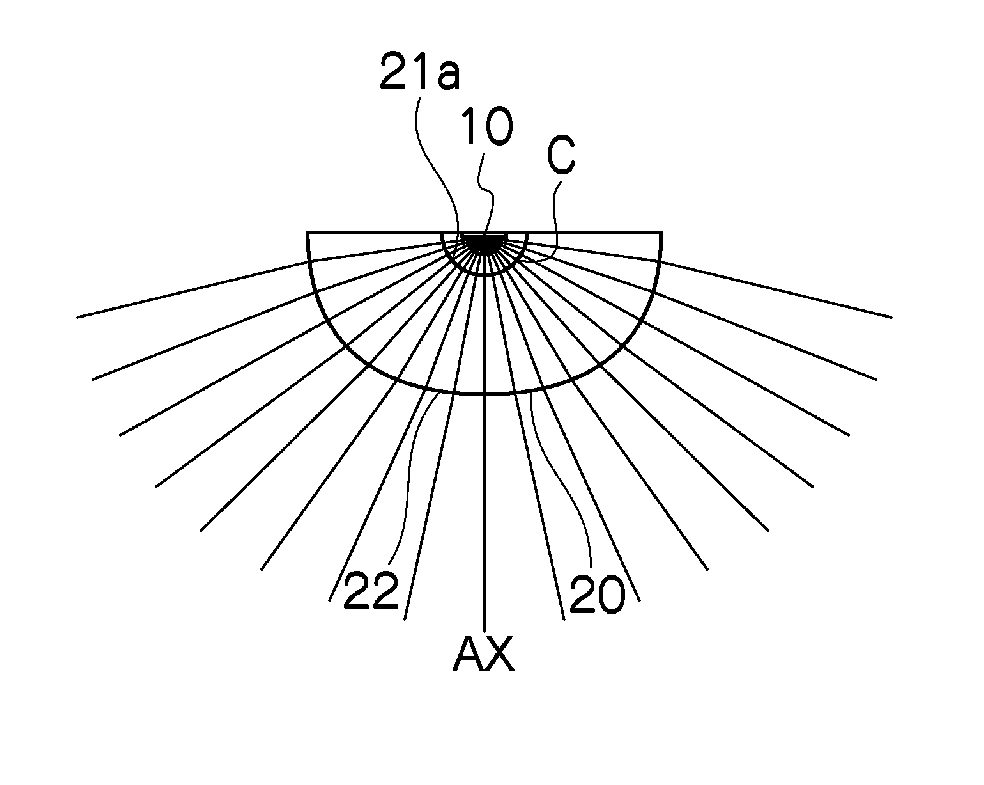
A lighting device 100 according to the present exemplary embodiment (hereinafter, referred to as an optical module 100) can be suitably applied to a road illumination light, a sidewalk light, a parking light, and the like. As shown in FIGS. 3 and 4A to 4C, the optical module 100 can include an LED light source 10 and a lens body 20 disposed in front of the LED light source 10 and be opposed to the LED light source 10. It should be understood that the plurality of radially extending lines on the lens body 20 in FIG. 3 are virtual lines for showing the three dimensional appearance of the lens body 20.

The LED light source 10 can be a white LED light source, for example.

As shown in FIGS. 4B and 4C, the lens body 20 can be disposed so as to be opposite to the LED light source 10 and can be a solid lens body...


PUM


Abstract

A lighting fixture can have a reduced depth size. The lighting device can include an LED light source, and a lens body disposed in front of the LED light source to be opposed to the LED light source. The lens body can includes a front light exiting surface and a rear surface that includes a light incident surface on which light emitted from the LED light source can be incident. The light incident surface can be a cylindrically recessed light incident surface that is formed by moving a concave semicircle section with respect to the LED light source in one direction to define a recessed space, and the LED light source is disposed within the recessed space defined by the light incident surface so that the light emitted from the LED light source is incident on the light incident surface.

Description

This application claims the priority benefit under 35 U.S.C. §119 of Japanese Patent Application No. 2010-070048 filed on Mar. 25, 2010, which is hereby incorporated in its entirety by reference.TECHNICAL FIELDThe presently disclosed subject matter relates to a lighting device, and in particular, to a lighting device to be disposed at a lower position.BACKGROUND ARTLighting devices with a projector type optical system have been proposed as conventional lighting devices for street lights (see, for example, Japanese Patent Application Laid-Open No. 2003-36705).For example, as shown in FIG. 1, a lighting device 400 disclosed in Japanese Patent Application Laid-Open No. 2004-36705 can include a light source 410, a reflecting mirror 420 configured to converge light beams from the light source 410 and a projector lens 430 configured to convert the converged light beams from the light source 410 by the reflecting mirror 420 to parallel light beams so as to project the parallel light beams ...

Claims


Application Information

Patent Timeline
Patent Type & Authority Applications(United States)
IPC IPC(8): F21V17/02F21V5/00
CPCF21S2/005F21S8/081F21V5/04F21V29/74F21Y2101/02G02B19/0014G02B19/0061F21W2131/103F21Y2115/10
Inventor KOIKE, TERUOMORIGUCHI, SATOSHI
Owner STANLEY ELECTRIC CO LTD
Why Eureka
Try Eureka