
Display device

a display device and display technology, applied in the field of directviewing display devices, can solve problems such as visible joints between the plurality of display devices

Active Publication Date: 2011-10-06
SHARP KK
View PDF1 Cites 95 Cited by
  • Summary
  • Abstract
  • Description
  • Claims
  • Application Information

AI Technical Summary

Benefits of technology

The present invention provides a direct-viewing type display device that can display a jointless image even when tiled in two directions with a plurality of display panels. The device includes a display panel with a display region and a frame region, and a light-transmitting cover disposed on a viewer's side of the display panel. The display region is composed of a peripheral display region adjoining the frame region and a central display region. The peripheral display region includes a first peripheral display section surrounded by a straight line passing through a point where border lines intersect. The at least one light-transmitting cover includes a lens portion that functions as a lens to refract light from pixels in the peripheral display region towards the frame region. This results in an image that is also displayed on the front face of the frame region, so that a jointless image is displayed on the entire screen.

Problems solved by technology

However, using the tiling technique has a problem of visible joints between the plurality of display devices.
This problem is not limited to liquid crystal display devices, but is a problem common to direct-viewing type display devices, e.g., PDPs, organic EL display devices, and electrophoresis display devices.

Method used


Image

  • Display device
  • Display device
  • Display device

Examples


Embodiment Construction

[0050]Hereinafter, an embodiment of the present invention will be described with reference to the drawings. However, the present invention is not limited to the illustrated embodiment.

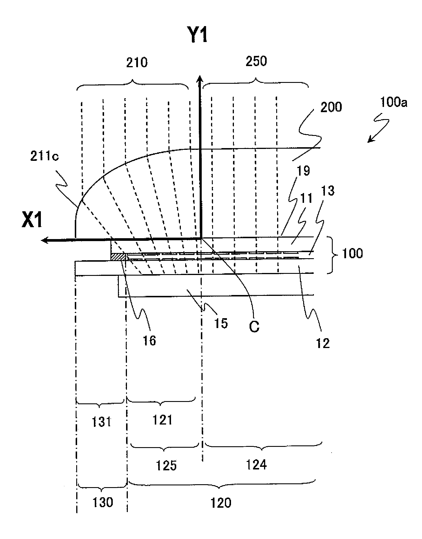
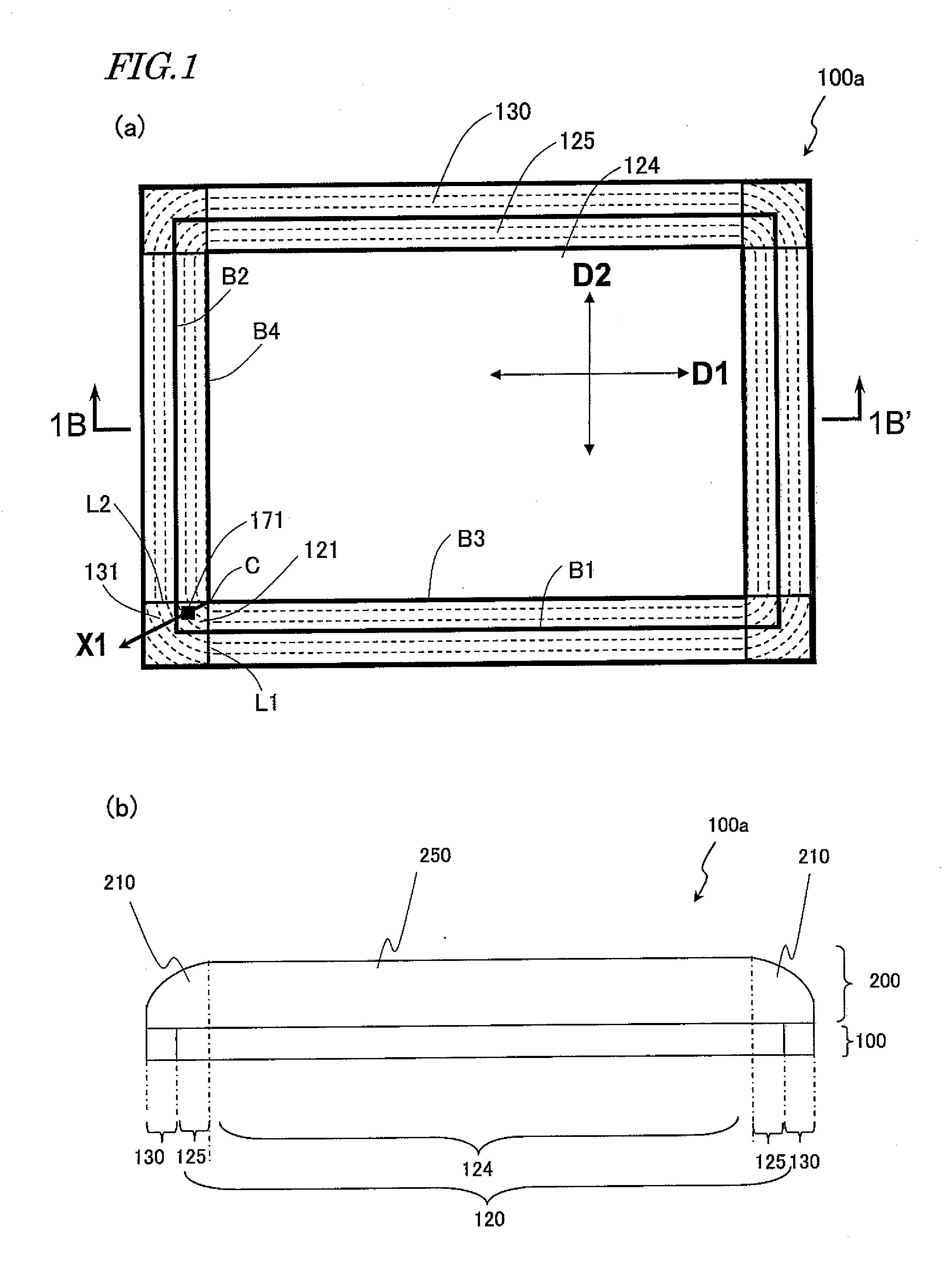
[0051]FIG. 1 schematically shows a direct-viewing type liquid crystal display device 100a according to an embodiment of the present invention. FIG. 1(a) is a schematic upper plan view of the liquid crystal display device 100a as seen from the viewer's side, and FIG. 1(b) is a schematic cross-sectional view along line 1B-1B′ in FIG. 1(a).

[0052]As shown in FIGS. 1(a) and (b), the liquid crystal display device 100a includes a liquid crystal display panel 100 and a light-transmitting cover 200 which is provided on the viewer's side of the liquid crystal display panel 100. The liquid crystal display panel 100 includes a display region 120 in which a plurality of pixels are arranged in a matrix array having rows and columns, and a frame region 130 provided outside the display region 120. The display region 1...


PUM


Abstract

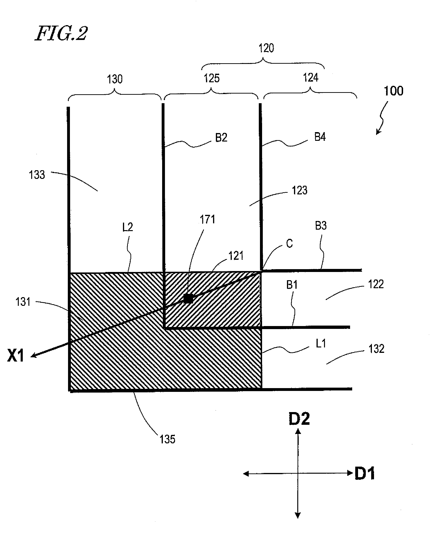
A direct-viewing type display device 100a includes a display panel 100 having a display region 120 including pixels arrayed in a row direction and a column direction and a frame region 130 provided outside the display region, such that a first border line B1 and a second border line B2 exist between the display region and the frame region; and a light-transmitting cover 200 disposed on the viewer's side. The display region includes a peripheral display region 125 and a central display region 124; a third border line B3 and a fourth border line B4 exist between the peripheral display region and the central display region; the peripheral display region includes a first peripheral display section 121; the light-transmitting cover includes a lens portion disposed over the peripheral display region and the frame region; and the lens portion refracts light going out from a pixel 171 within the first peripheral display section in a direction X1 from a point where the third border line and the fourth border line intersect toward the pixel 171. According to the present invention, a display device is provided whose entire frame region including the corner portions can be obscured, such that joints can be obscured in the case of tiling.

Description

TECHNICAL FIELD[0001]The present invention relates to a display device, and more particularly to a direct-viewing type display device.BACKGROUND ART[0002]Conventionally, in television sets and display devices for displaying information, attempts of arraying a plurality of display devices (which may be referred to as a tiling technique) to realize a pseudo large-screen display device are being made. However, using the tiling technique has a problem of visible joints between the plurality of display devices.[0003]This problem will be described by taking a liquid crystal display device for example. A liquid crystal display device includes a liquid crystal display panel, a backlight device, circuits for supplying various electrical signals to the liquid crystal display panel, and a power supply, as well as a housing in which to accommodate these. The liquid crystal display panel includes a pair of glass substrates and a liquid crystal layer provided between them. On one of the pair of g...

Claims


Application Information

Patent Timeline
Patent Type & Authority Applications(United States)
IPC IPC(8): G02B27/02
CPCG02B17/0884G02B27/024G02B27/095H04N2201/0089G02F1/133526G02F2001/133331G02F2001/133388G02F1/13336G02F1/133331G02F1/133388
Inventor WATANABE, HISASHI
Owner SHARP KK
Learn More