Apparatus, process, and program for image encoding

a technology of image encoding and process, applied in the field of apparatus and a process for image encoding, can solve the problems of insufficient reduction of video data amount, inability to apply low-pass filtering to the region of interest, and large amount of data to be stored, so as to increase the calculation burden and high image compression

Inactive Publication Date: 2011-10-06
FUJIFILM CORP
View PDF3 Cites 43 Cited by
  • Summary
  • Abstract
  • Description
  • Claims
  • Application Information

AI Technical Summary

Benefits of technology

[0050]In the image encoding apparatus according to the present invention having the feature (xv), the image size is changed on the basis of the target image quality, and is actually reduced, before performing processing for compression, so as t

Problems solved by technology

For example, in the crime prevention camera systems, the time for which video data is recorded is long, so that the amount of data to be stored becomes massive.
However, according to the technique disclosed in U.S. Pat. No. 7,801,337, the filtering with the low-pass filter is not applied to the region of interest.
Therefore, there is a possibility that the amount of video data cannot be sufficiently r

Method used


Image

  • Apparatus, process, and program for image encoding
  • Apparatus, process, and program for image encoding
  • Apparatus, process, and program for image encoding

Examples


first embodiment

1. First Embodiment

1.1 System Configuration

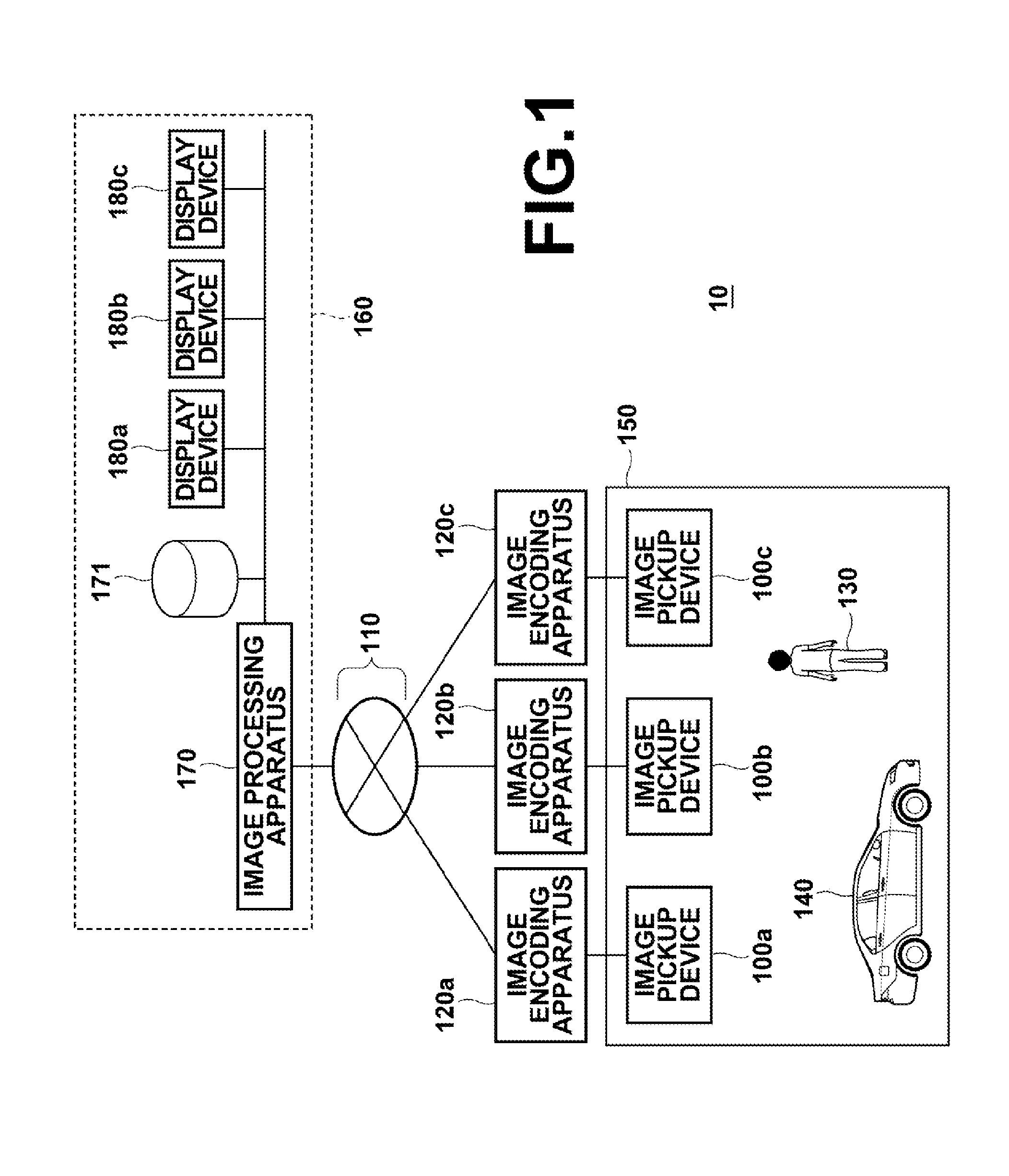
[0070]FIG. 1 is a diagram schematically illustrating an outline of a configuration of the image processing system 10 according to the first embodiment of the present invention. The image processing system 10 reduces the amount of data representing an image while maintaining the quality of the image of the object.

[0071]As illustrated in FIG. 1, the image processing system 10 comprises a plurality of image pickup devices 100a, 100b, and 100c (which may be hereinafter collectively referred to as the image pickup devices 100), a plurality of image encoding apparatuses 120a, 120b, and 120c (which may be hereinafter collectively referred to as the image encoding apparatuses 120), an image processing apparatus 170, a communication network 110, an image database (DB) 171, and a plurality of display devices 180a, 180b, and 180c (which may be hereinafter collectively referred to as the display devices 180). The image pickup devices 100 each pick up a...

second embodiment

2. Second Embodiment

2.1 Functions of Second Embodiment

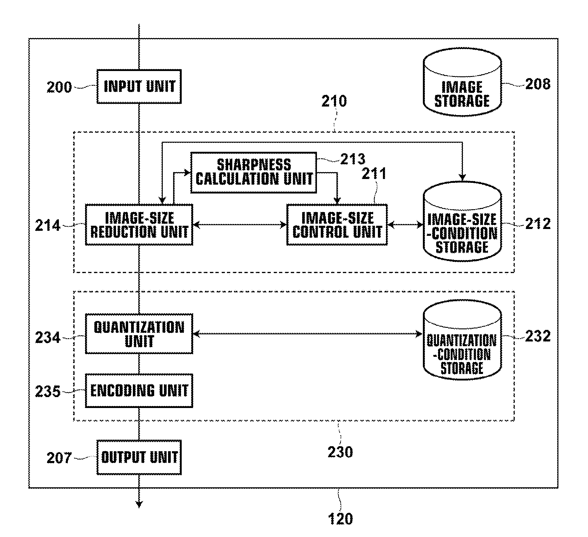
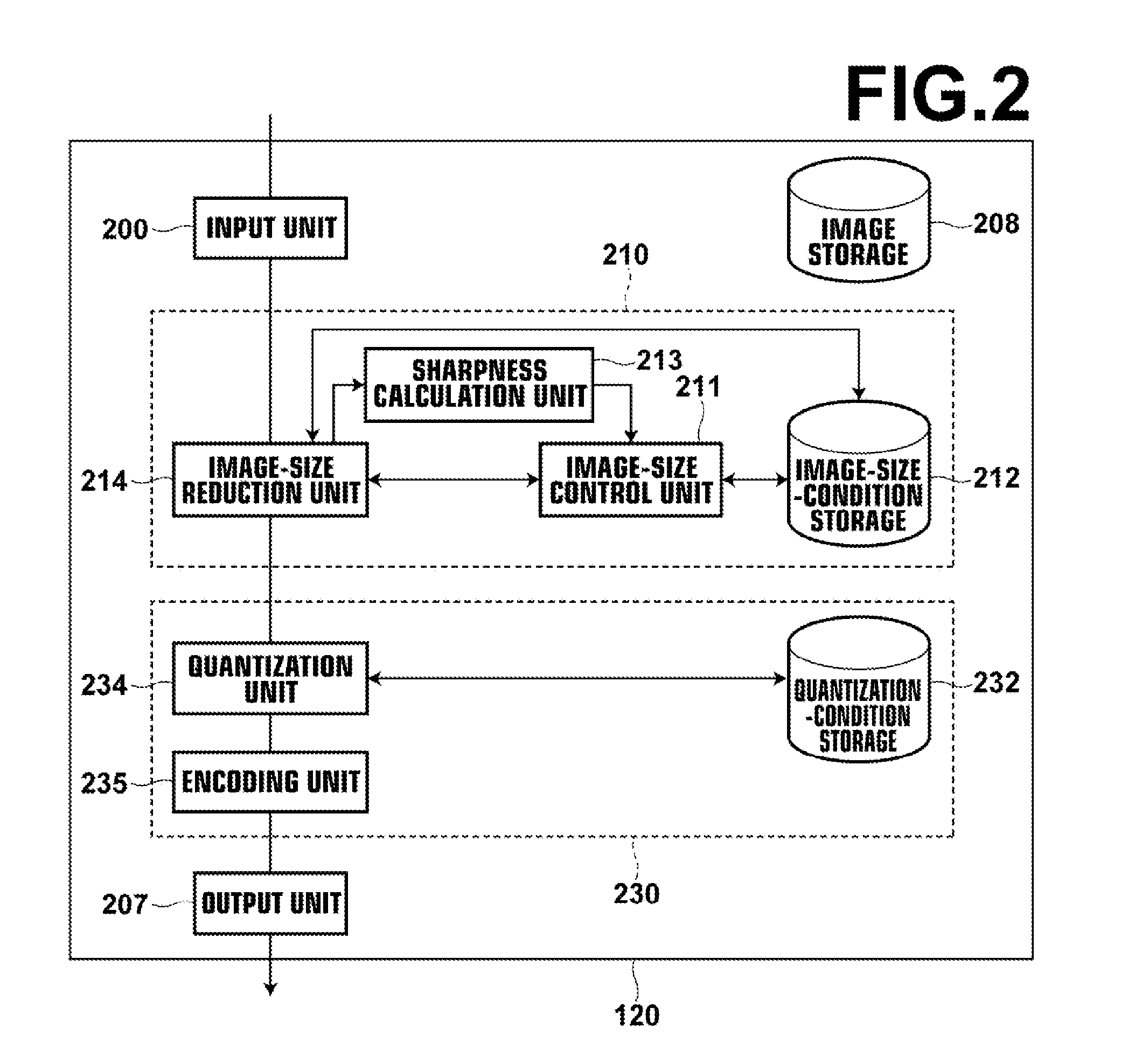
[0125]FIG. 6 is a block diagram illustrating functions of an image encoding apparatus 120-2 according to the second embodiment, which can be used as one of the image encoding apparatuses 120a, 120b, and 120c in the configuration of the image processing system 10 illustrated in FIG. 1.

[0126]As illustrated in FIG. 6, the image encoding apparatus 120-2 comprises a region-of-interest detection unit 203 and a region-of-interest separation unit 204 in addition to the functions of the image encoding apparatus 120 according to the first embodiment. The region-of-interest detection unit 203 detects a plurality of regions of interest respectively receiving different degrees of interest from an inputted image or a reduced image of the inputted image (in which the image size is reduced). The region-of-interest separation unit 204 generates region-of-interest images respectively representing the plurality of regions of interest from the input...

third embodiment

3. Third Embodiment

[0148]FIG. 11 is a block diagram illustrating functions of an image encoding apparatus 120-3 according to the third embodiment, which can be used as one of the image encoding apparatuses 120a, 120b, and 120c in the configuration of the image processing system 10 illustrated in FIG. 1.

[0149]As illustrated in FIG. 11, the image encoding apparatus 120-3 comprises an interframe-compression processing unit 240. The interframe-compression processing unit 240 includes an interframe-compression-condition storage 242 and an interframe compression unit 241. The interframe-compression-condition storage 242 stores an interframe-compression condition, which is a condition for compressing each of portions (region-of-interest videos) of a video image respectively corresponding to a plurality of regions of interest along the time direction, where the video image is constituted by a plurality of (constituent) frames which are inputted into the image encoding apparatus 120-3. The i...


PUM


Abstract

In an image encoding process for encoding data of an inputted image and outputting encoded image data: an image-size condition including image size and target sharpness is stored in an image-size-condition storage; a reduced image of the inputted image having the above image size included in the image-size condition stored in the image-size-condition storage is produced; and the sharpness of the reduced image is calculated. When the calculated sharpness of the reduced image is higher than the target sharpness, the image size included in the image-size condition stored in the image-size-condition storage is reduced, and a further reduced image of the inputted image having the reduced image size is produced.

Description

BACKGROUND OF THE INVENTION[0001]1. Field of the Invention[0002]The present invention relates to an apparatus and a process for image encoding, and a computer-readable non-transitory medium storing an image encoding program for making a computer execute the process for image encoding.[0003]2. Description of the Related Art[0004]Currently, development of the digital recording technology (such as MPEG) for recording video images taken by crime prevention cameras and the like is proceeding. Although video recording can be realized by storing video data in recording media such as HDDs (hard disk drives), opto-magnetic disks, and the like, the volume occupied by the video data in the recording media varies with the compression ratio of the video data even when the recording time is unchanged. For example, in the crime prevention camera systems, the time for which video data is recorded is long, so that the amount of data to be stored becomes massive. Therefore, it is necessary to increas...

Claims


Application Information

Patent Timeline
IPC IPC(8): G06K9/36H04N7/26H04N5/765H04N5/781H04N19/00H04N5/92H04N7/18H04N19/132H04N19/134H04N19/167H04N19/172H04N19/196H04N19/20H04N19/503H04N19/587H04N19/59H04N19/60H04N19/61
CPCH04N19/176H04N19/46H04N19/102H04N19/124H04N19/132H04N19/31H04N19/137H04N19/154H04N19/17H04N19/33H04N19/136
Inventor NOGUCHI, YUKINORI
Owner FUJIFILM CORP
Why Eureka
Try Eureka