Fly-height control using asynchronous sampling

Active Publication Date: 2011-10-13
AVAGO TECH INT SALES PTE LTD
View PDF2 Cites 11 Cited by
  • Summary
  • Abstract
  • Description
  • Claims
  • Application Information

AI Technical Summary

Benefits of technology

[0013]In one embodiment, the present invention is a method usable to control fly height of a head over a medium in a data storage device. The method comprises determining, in a read-back mode, a first value based on a first signal received by a read path of the data storage device. The first signal corresponds to pre-recorded data read from the medium and is characterized by at least one periodic pattern. The first value is generated by sampling the first signal at a first sampling frequency. The method further comprises determining, in a loop-back mode, a second value based on a second signal received by the read path directly from a write path of the data storage device. The second signal bypasses the medium and is characterized by the at least one periodic pattern. The second value is generated by sampling the second signal at a second sampling frequency different from the first sampling frequency. The method yet further comprises generating a third value based on the first and second values, wherein the third value is usable to control the fly height.
[0014]In another embodiment, the present invention is an apparatus usable to control fly height of a head over a medium in

Problems solved by technology

However, reducing the fly height too significantly can result in the read and/or write element contacting the surface of the platter.
Such contact is typically undesired because it may corrupt data stored on the platter and possibly even damage the platter and/or heads.
However, during operation, fly height may change due to environmental conditions such as temperature and/or voltage variations.
The write current may ca

Method used


Image

  • Fly-height control using asynchronous sampling
  • Fly-height control using asynchronous sampling
  • Fly-height control using asynchronous sampling

Examples


Embodiment Construction

[0023]Reference herein to “one embodiment” or “an embodiment” means that a particular feature, structure, or characteristic described in connection with the embodiment can be included in at least one embodiment of the invention. The appearances of the phrase “in one embodiment” in various places in the specification are not necessarily all referring to the same embodiment, nor are separate or alternative embodiments necessarily mutually exclusive of other embodiments. The same applies to the term “implementation.”

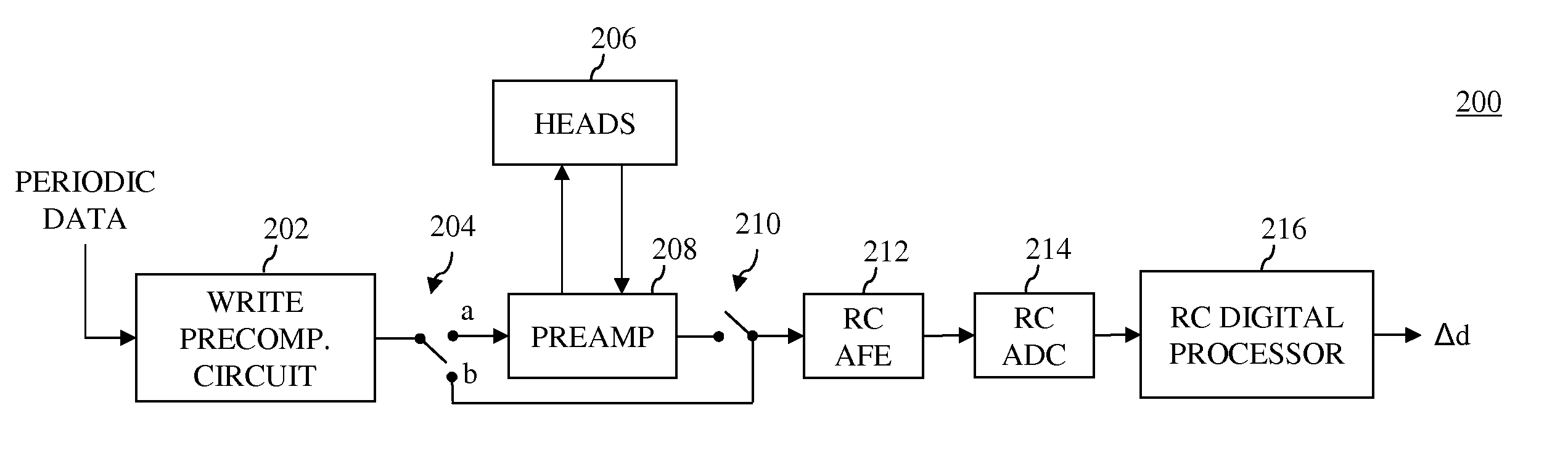
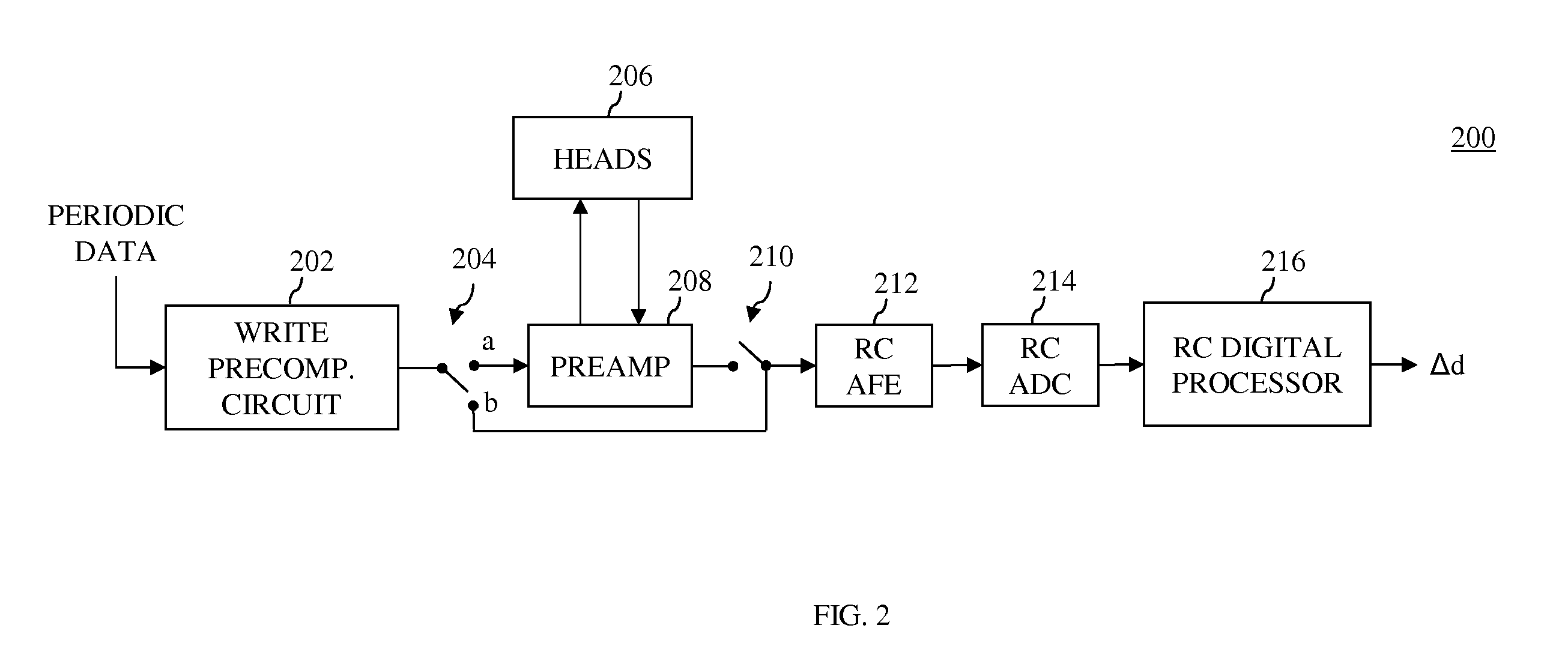
[0024]FIG. 2 shows a simplified block diagram of at least part of one implementation of a hard-disk drive (HDD) system 200. HDD system 200 has components that may be used to control the fly height of one or more heads over the medium (e.g., one or more platters). In general, HDD system 200 uses two modes to control fly height: a read-back mode and a loop-back mode. In the read-back mode, heads 206 and preamplifier 208 are connected in-line and write precompensation circuit ...


PUM


Abstract

In one embodiment, a hard-disk drive system performs fly-height control using a read-back mode and a loop-back mode. The read-back mode measures first and second harmonics pre-recorded on the medium and divides the first measurement by the second to obtain a read-back mode harmonic ratio. The loop-back mode measures the same first and second harmonics; however, the harmonics are provided by a write precompensation circuit rather than the medium. Further, the loop-back mode measurements are performed using asynchronous sampling to address aliasing and quantization errors. The first measurement is divided by the second to generate a loop-back harmonic ratio. In logarithm domain, the loop-back ratio is subtracted from the read-back mode ratio to remove environment-induced variations in the read path electronic circuits. The resulting harmonic ratio is subtracted from an initial harmonic ratio determined, for example, during manufacturing, to determine how much the harmonic ratio has changed.

Description

BACKGROUND OF THE INVENTION[0001]1. Field of the Invention[0002]The present invention relates to hard-disk drive (HDD) systems, and, in particular, to controlling fly height in such systems.[0003]2. Description of the Related Art[0004]In hard-disk drive (HDD) systems, the spacing between (i) the element of a read / write head and (ii) the surface of the platter, commonly referred to as fly height, is an important parameter affecting both capacity and performance. In general, reducing fly height during writing and / or reading operations improves bit-error rate. However, reducing the fly height too significantly can result in the read and / or write element contacting the surface of the platter. Such contact is typically undesired because it may corrupt data stored on the platter and possibly even damage the platter and / or heads.[0005]Typically, fly height is set during manufacturing. However, during operation, fly height may change due to environmental conditions such as temperature and / o...

Claims


Application Information

Patent Timeline
IPC IPC(8): G11B21/02
CPCG11B5/012G11B5/6064G11B5/6029G11B21/02G11B21/21
Inventor MATHEW, GEORGEGRUNDVIG, JEFFREYSONG, HONGWEILEE, YUAN XING
Owner AVAGO TECH INT SALES PTE LTD
Why Eureka
Try Eureka