Umbilical member arrangement unit of robot arm section

a technology of arrangement unit and umbilical member, which is applied in the direction of joints, manipulators, manufacturing tools, etc., can solve the problems of troublesome operation for an operator and the impact of the durability of the umbilical member, and achieve the effect of avoiding interferen

Active Publication Date: 2011-10-20
FANUC LTD
View PDF14 Cites 19 Cited by
  • Summary
  • Abstract
  • Description
  • Claims
  • Application Information

AI Technical Summary

Benefits of technology

Therefore, an object of the present invention is to provide an umbilical member arrangement unit of a robot arm section, capable of effectively avoiding interference between the umbilical member and external equipment, without using a guide member or the like.

Problems solved by technology

Therefore, excess force may be applied to the restrained portion of the umbilical member, and thus the durability of the umbilical member may be affected.
Further, when the umbilical member is replaced with another, removing and attaching operations of the umbilical member relative to the guide member must be carried out, such operations are troublesome for an operator.

Method used


Image

  • Umbilical member arrangement unit of robot arm section
  • Umbilical member arrangement unit of robot arm section
  • Umbilical member arrangement unit of robot arm section

Examples


Embodiment Construction

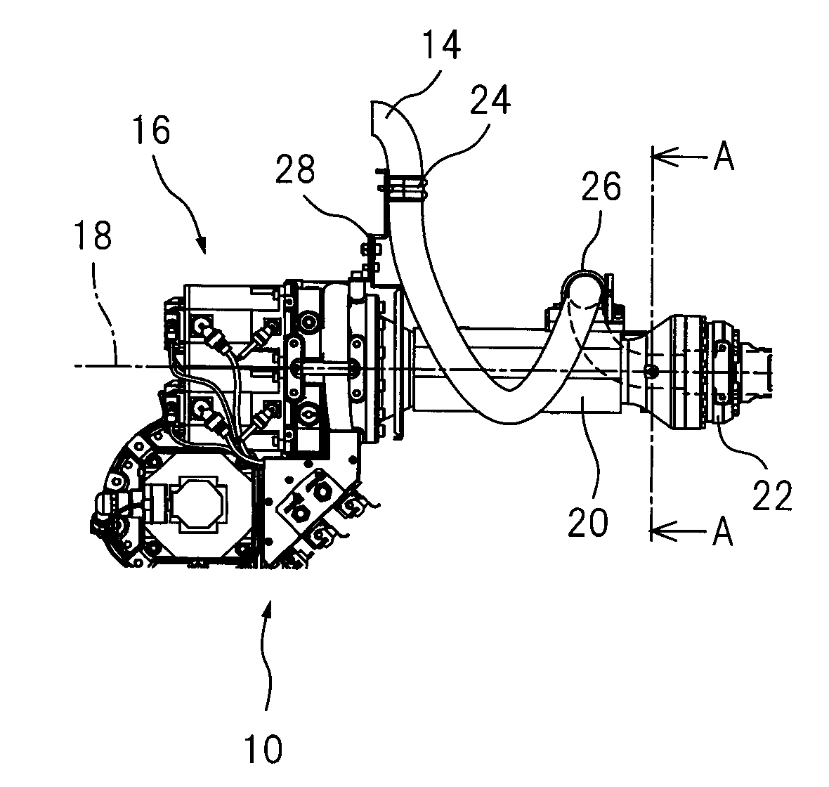
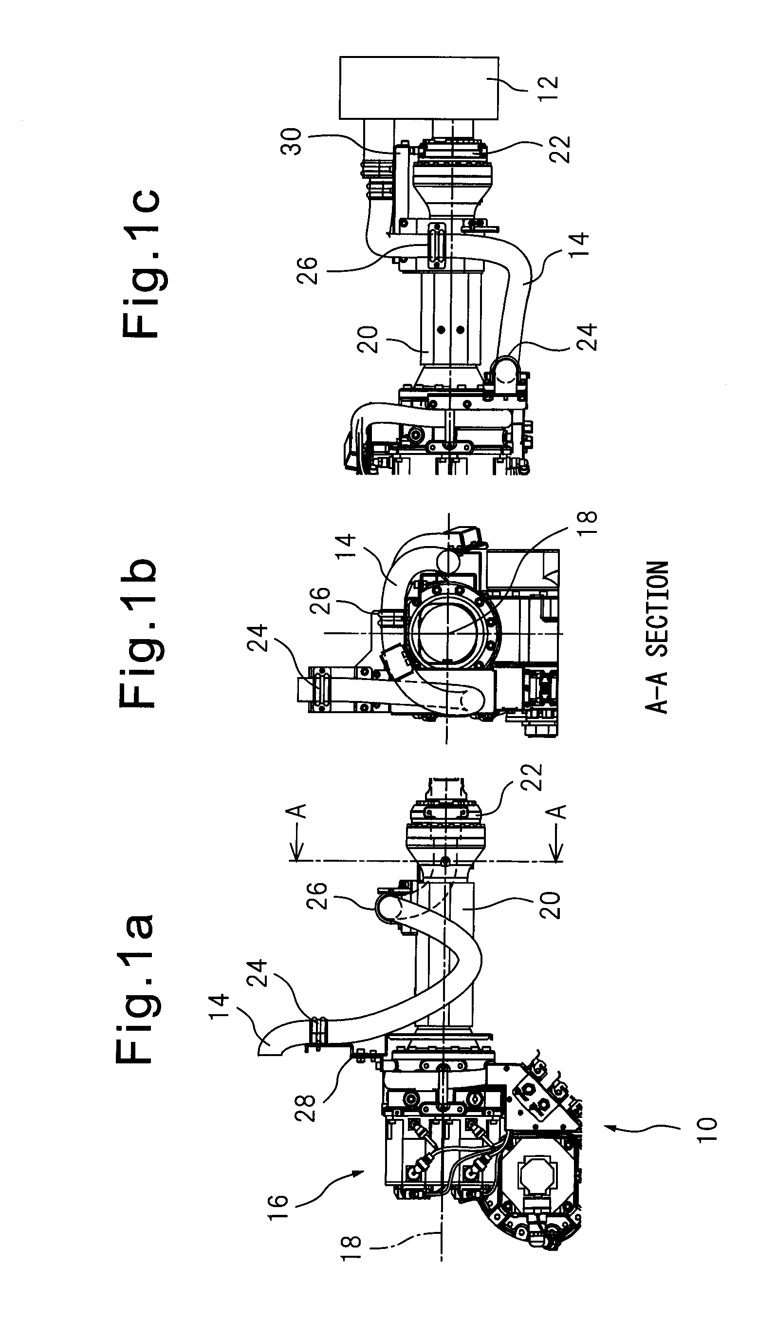
FIGS. 1a to 1c show a preferred embodiment of the invention; concretely, a side view (FIG. 1a) of an arrangement unit for an umbilical member 14 extending to an end effector 12 attached to a front end of a wrist section via a forearm 10 of an industrial robot, a cross-sectional view (FIG. 1b) along A-A line of FIG. 1a, and a top view (FIG. 1c) of the configuration of FIG. 1a. Forearm 10 has an arm section 20 having generally a cylindrical or a truncated cone shape and extending along a longitudinal axis 18 of forearm 20 from a base section 16. At a front end of arm section 20, a wrist section or rotating part 22 is attached rotatably about longitudinal axis 18.

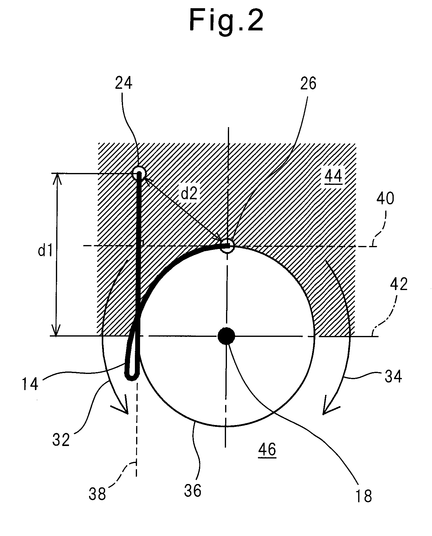
Umbilical member 14 is a flexible member including at least one of a cable adapted to supply power or a signal to end effector 12 and a tube adapted to supply coolant or activation air to end effector 12. As described below, it is preferable that the umbilical member is not fully flexible, and has a certain degree of elasticit...


PUM


Abstract

An umbilical member arrangement unit of a robot arm section, capable of avoiding interference between the umbilical member and external equipment without using a guide member. The arrangement unit has a first fixing member attached to a nonrotating part and adapted to nonslidably fix the umbilical member, and a second fixing member attached to a rotating part so as to integrally rotate with the rotating part and adapted to nonslidably fix the umbilical member. When the rotating part is positioned at a center position of a rotational motion range thereof about the longitudinal axis, the first and second fixing members direct the umbilical member along first and second tangential lines, respectively, the two tangential lines being generally perpendicular to each other, and, the fixing members are positioned in the same region in relation to two regions defined by a boundary plane parallel to the second tangential line, on which the longitudinal axis lies.

Description

RELATED APPLICATIONSThe present application claims priority from Japanese Patent Application No. 2010-93219, filed on Apr. 14, 2010, the entire contents of which are fully incorporated herein by reference.BACKGROUND OF THE INVENTION1. Field of the InventionThe preset invention relates to an arrangement unit for an umbilical member arranged at a robot arm section of an industrial robot.2. Description of the Related ArtWhen an industrial robot is used for an operation, the robot is required to be provided with an umbilical member including a cable for transmitting power or a signal and / or a tube for transmitting coolant or activation gas to a hand or a welding gun attached to the end of a wrist section of the robot, via a forearm of the robot. It is necessary that the umbilical member, arranged around the forearm of the robot, has a certain amount of extra length (margin) so that excess force is not applied to the umbilical member while the rotation of the forearm. On the other hand, ...

Claims


Application Information

Patent Timeline
Patent Type & Authority Applications(United States)
IPC IPC(8): B25J19/00
CPCB25J19/0025Y10T74/20311Y10S901/29
Inventor IBAYASHI, JUNJINUSHI, MUNEHIROKUME, HIROKAZU
Owner FANUC LTD
Why Eureka
Try Eureka