Demand based texture rendering in a tile based rendering system

a tile and texture technology, applied in the field of three-dimensional computer graphics rendering systems, can solve the problems of reducing the memory bandwidth associated with both the rendering of textures and their subsequent use, and achieve the effect of reducing the memory bandwidth

Inactive Publication Date: 2011-10-20
IMAGINATION TECH LTD
View PDF4 Cites 28 Cited by
  • Summary
  • Abstract
  • Description
  • Claims
  • Application Information

AI Technical Summary

Benefits of technology

[0011]Preferred embodiments of the present invention provide a method and apparatus that enable a tile based rendering system to rasterise and store rendered texture surfaces only where they are to be used by subsequent renders. This is accomplished in an embodiment of the invention by performing the tiling phase as described above for all texture surfaces but deferring the rasterisation phase of those dynamically rendered texture surfaces to the point at which they are referenced. As the rendering of the scene that uses the “demand based texture renders” (e.g. 100 from FIG. 1) potentially only references a small area of each texture within each tile the system can render one or more texture tiles at the point of reference into a small write back cache for immediate use within the main render. Due to the localised nature of the references it is highly likely that the rendered data will continue to reside within the cache subsystem for any tiles for which it is required, thereby substantially reducing the memory bandwidth associated with both the rendering of the textures and their subsequent use.

Problems solved by technology

Due to the localised nature of the references it is highly likely that the rendered data will continue to reside within the cache subsystem for any tiles for which it is required, thereby substantially reducing the memory bandwidth associated with both the rendering of the textures and their subsequent use.

Method used


Image

  • Demand based texture rendering in a tile based rendering system
  • Demand based texture rendering in a tile based rendering system
  • Demand based texture rendering in a tile based rendering system

Examples


Embodiment Construction

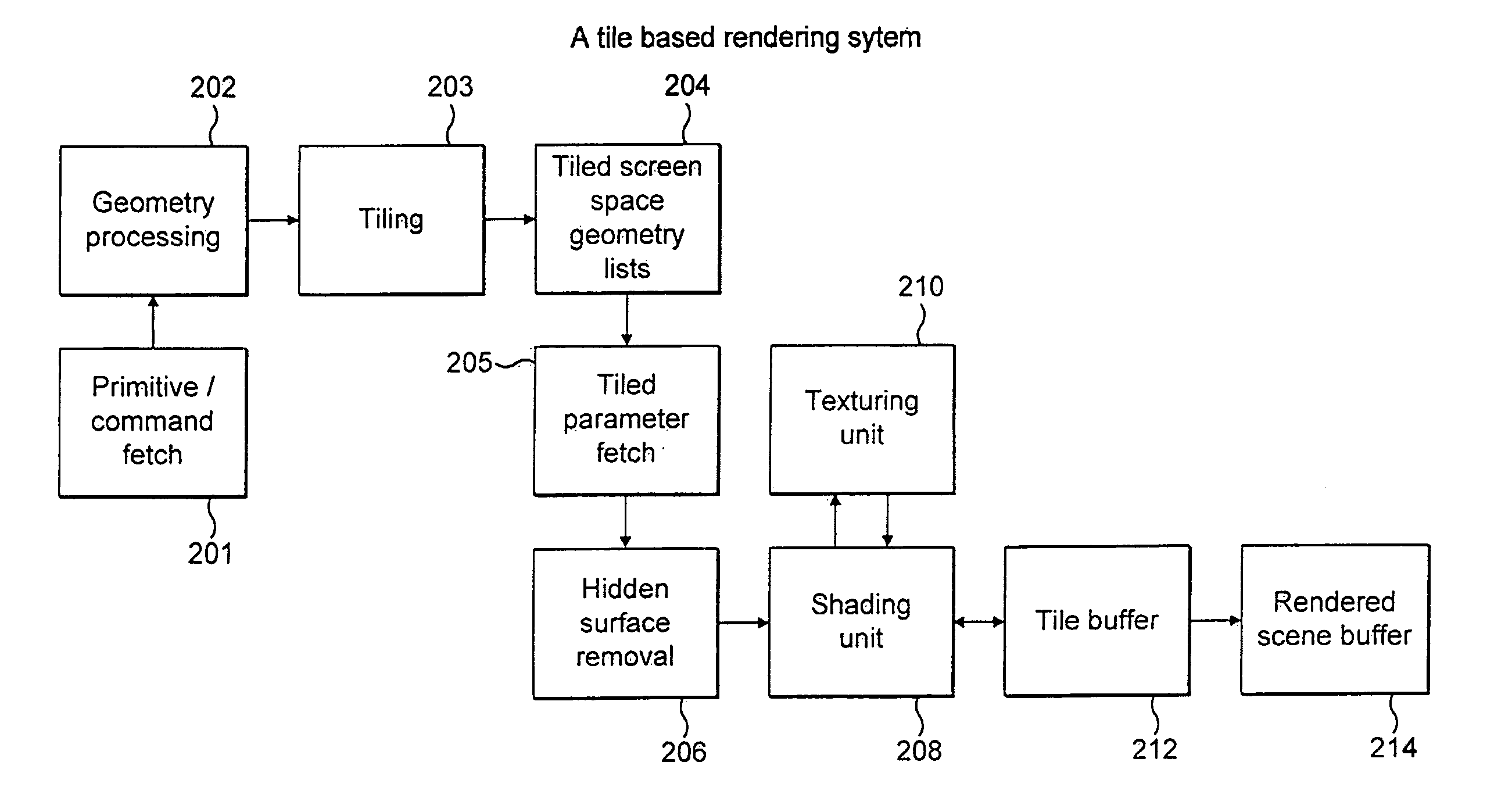
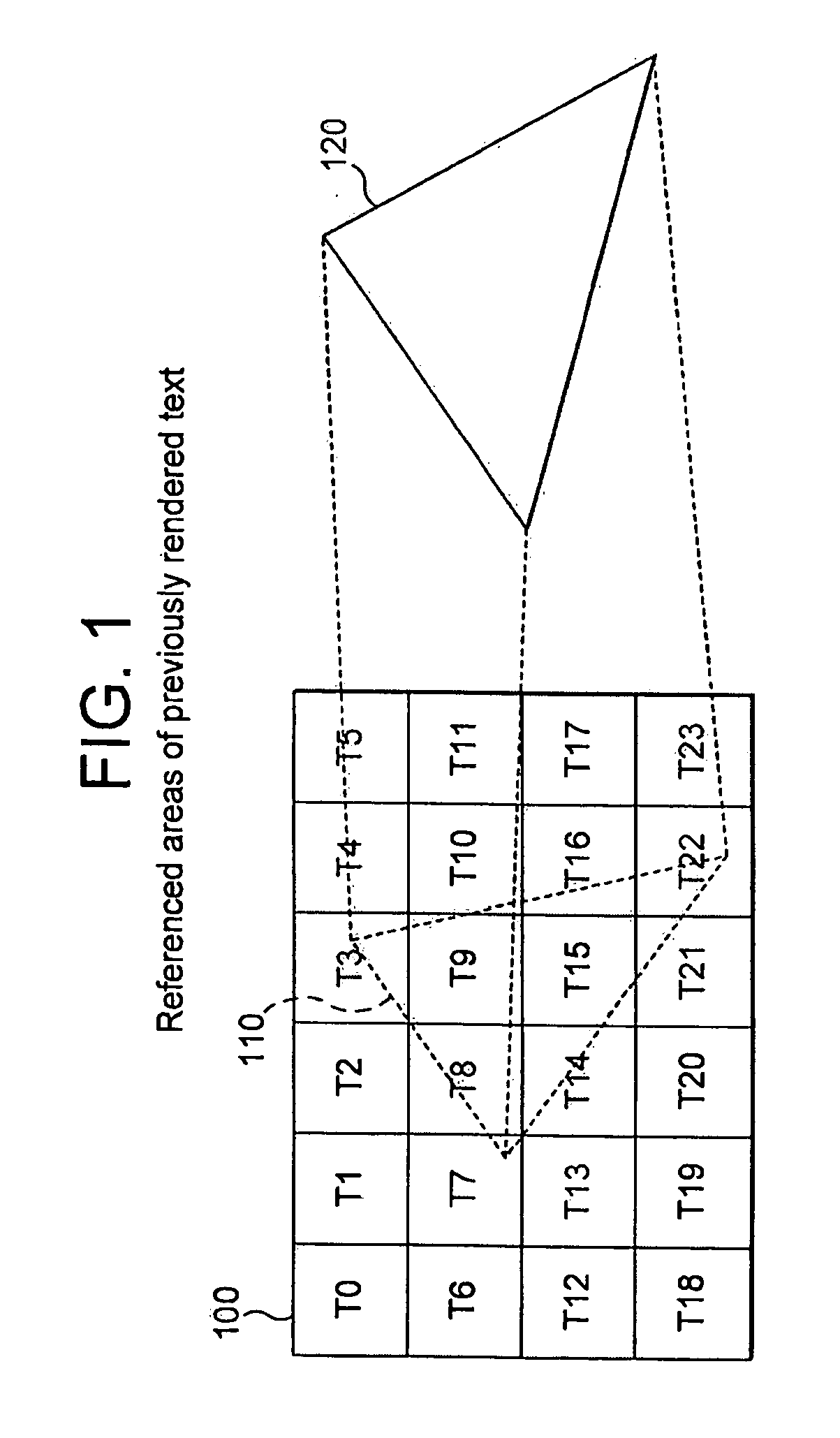
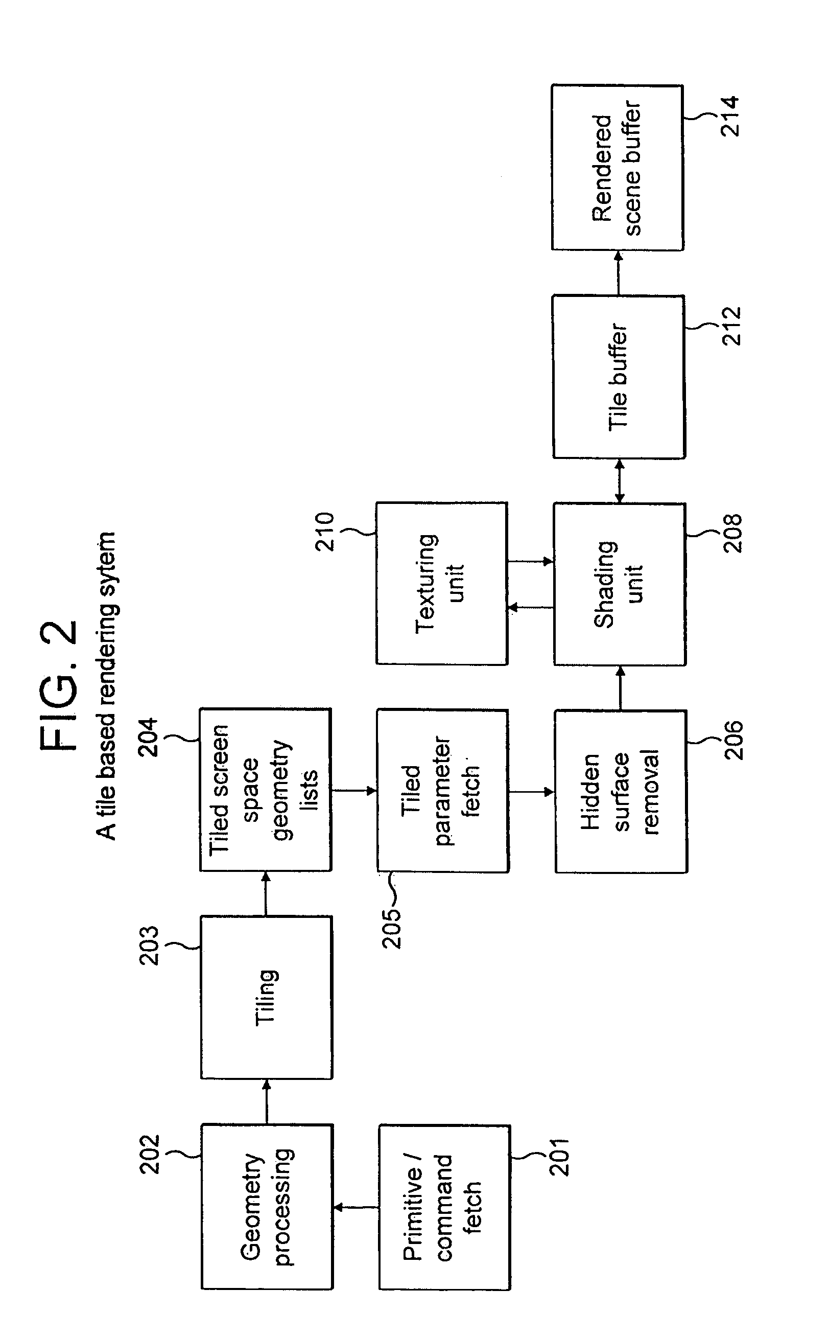
[0018]FIG. 3 illustrates the operation of demand mode texture rasterisation in a tile based system. An application 300 first generates geometry 305 for an image which is to be rendered to a texture as in 100 in FIG. 1. This geometry is processed at 310 using well known techniques to produce screen space geometry that is passed to a tiling unit 315 which generates tile screen space parameters 320 as described for a tile based rendering system. It should be noted that the current state of each tile within the texture i.e. if it has been rendered is indicated by a valid flags table 358. This table is generally stored within memory and contains a status flag for each tile that indicates if it has been rendered, all flags are initially cleared to indicate that no tiles have been rendered. Each time a tile is rendered a flag corresponding to that tile is set.

[0019]The application then switches to the rendering of a main scene at 330 by producing main scene geometry 335 which is then proce...


PUM


Abstract

A method and apparatus are provided for shading and texturing computer graphic images in a tile based rendering system using dynamically rendered textures. Scene space geometry is derived for a dynamically rendered texture and passed to a tiling unit which derives scene space geometry for a scene which references the textures. Scene space geometry for a scene that references the dynamically rendered texture is also derived and passed to the tiling unit. The tiling unit uses object data derived from the scene space geometry to detect reference to areas of dynamically rendered textures, as yet un-rendered. These are then dynamically rendered.

Description

FIELD OF THE INVENTION[0001]This invention relates to a three-dimensional computer graphics rendering system in particular to methods and apparatus associated with rendering of textures in a tile based rendering system.BACKGROUND TO THE INVENTION[0002]Within real time computer graphics it is common to perform renders to surfaces which can then be used as textures in subsequent renders i.e. the rendered surface becomes a new texture or a “Dynamically Rendered” texture. For example in order to render a scene that includes reflections of the scene it is common to first render the scene to an environment texture map. This map is then used during the shading of objects to produce a reflection of the environment on the objects. This may be used, for example to show a reflection in a mirrored building.[0003]In addition to environment mapping it is common for modern computer graphics applications to use a technique called shadow mapping. The shadow mapping technique renders the depth of obj...

Claims


Application Information

Patent Timeline
Patent Type & Authority Applications(United States)
IPC IPC(8): G09G5/00
CPCG06T15/04
Inventor HOWSON, JOHN WILLIAM
Owner IMAGINATION TECH LTD
Why Eureka
Try Eureka