Motion vector detector, method of detecting motion vector and image recording equipment

Inactive Publication Date: 2005-10-13
KK TOSHIBA
View PDF8 Cites 21 Cited by
  • Summary
  • Abstract
  • Description
  • Claims
  • Application Information

AI Technical Summary

Problems solved by technology

When the temporal distance to the reference picture becomes greater, the definition range needs to be enlarged in proportion to the square of the temporal distance, which involves an enormous amount of computation.
However, the motion estimator described in Japanese Laid-Open (Kokai) Patent Application 2000-287214 has some problems.
One problem is that there are an increasing number of operations for determining whether a motion estimation range based on a reference motion vector is included in a partial region of a reference picture stored in an LSI embedded memory.
Another problem is that when only a very small portion of the motion estimation range based on the referen

Method used


Image

  • Motion vector detector, method of detecting motion vector and image recording equipment
  • Motion vector detector, method of detecting motion vector and image recording equipment
  • Motion vector detector, method of detecting motion vector and image recording equipment

Examples


first embodiment

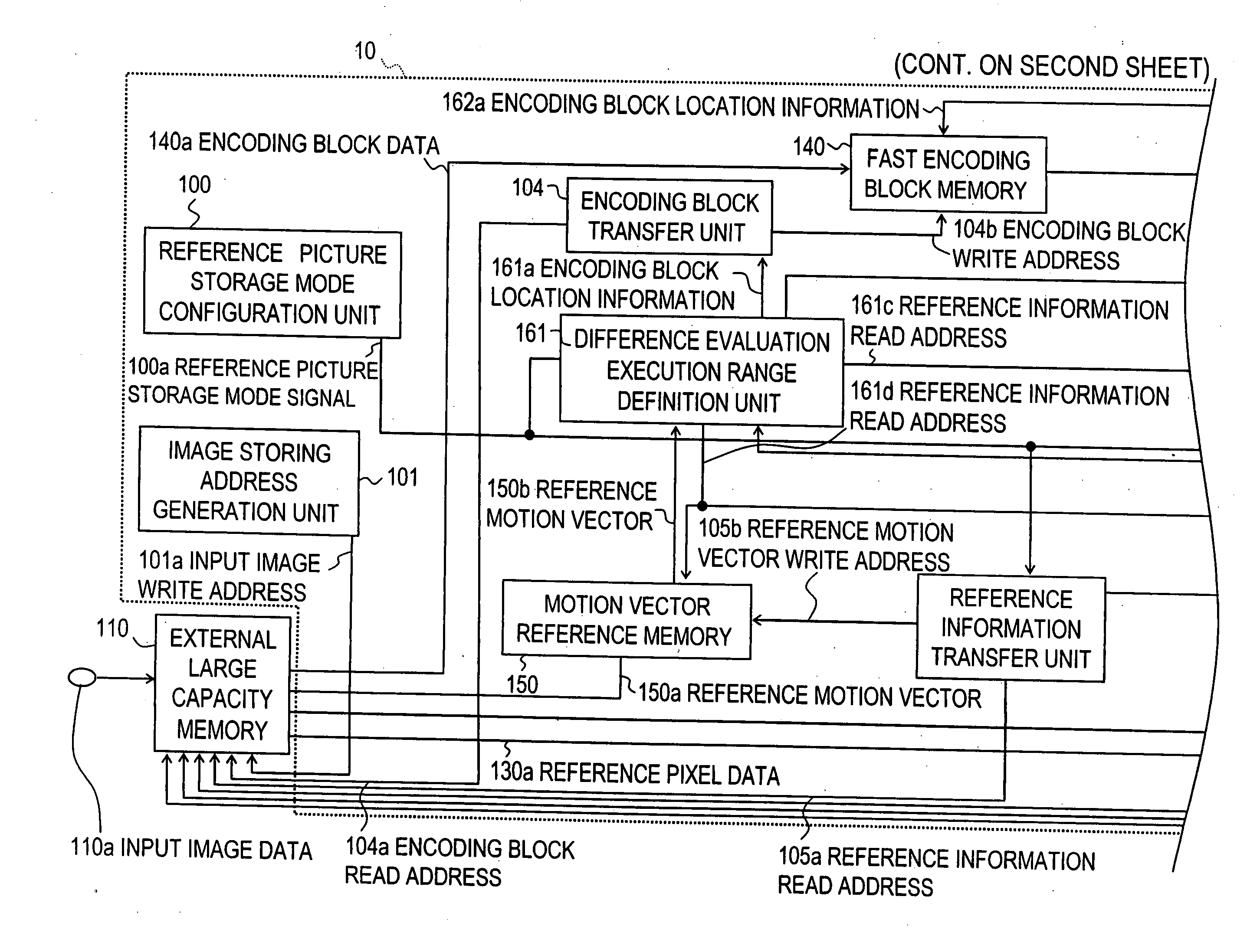
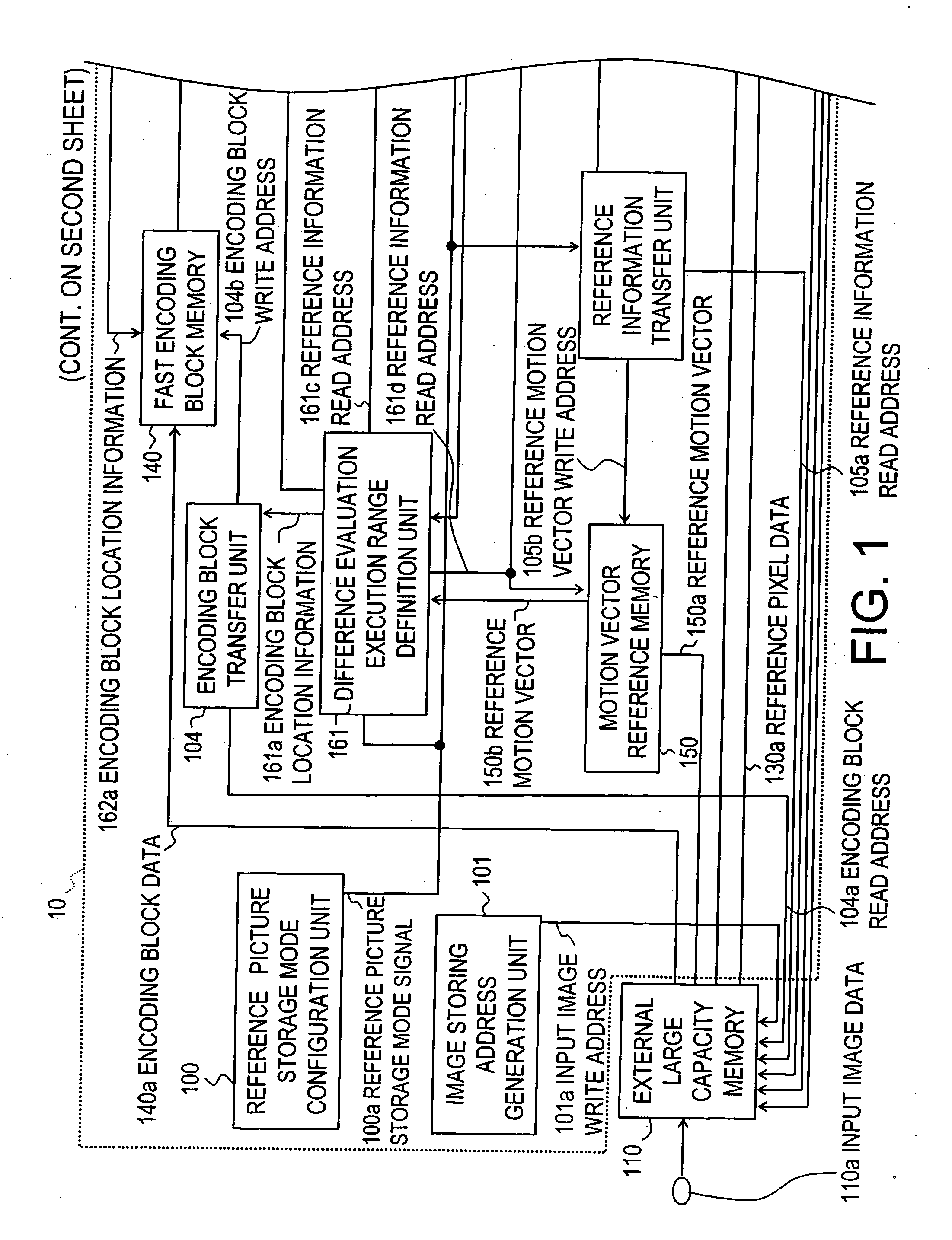
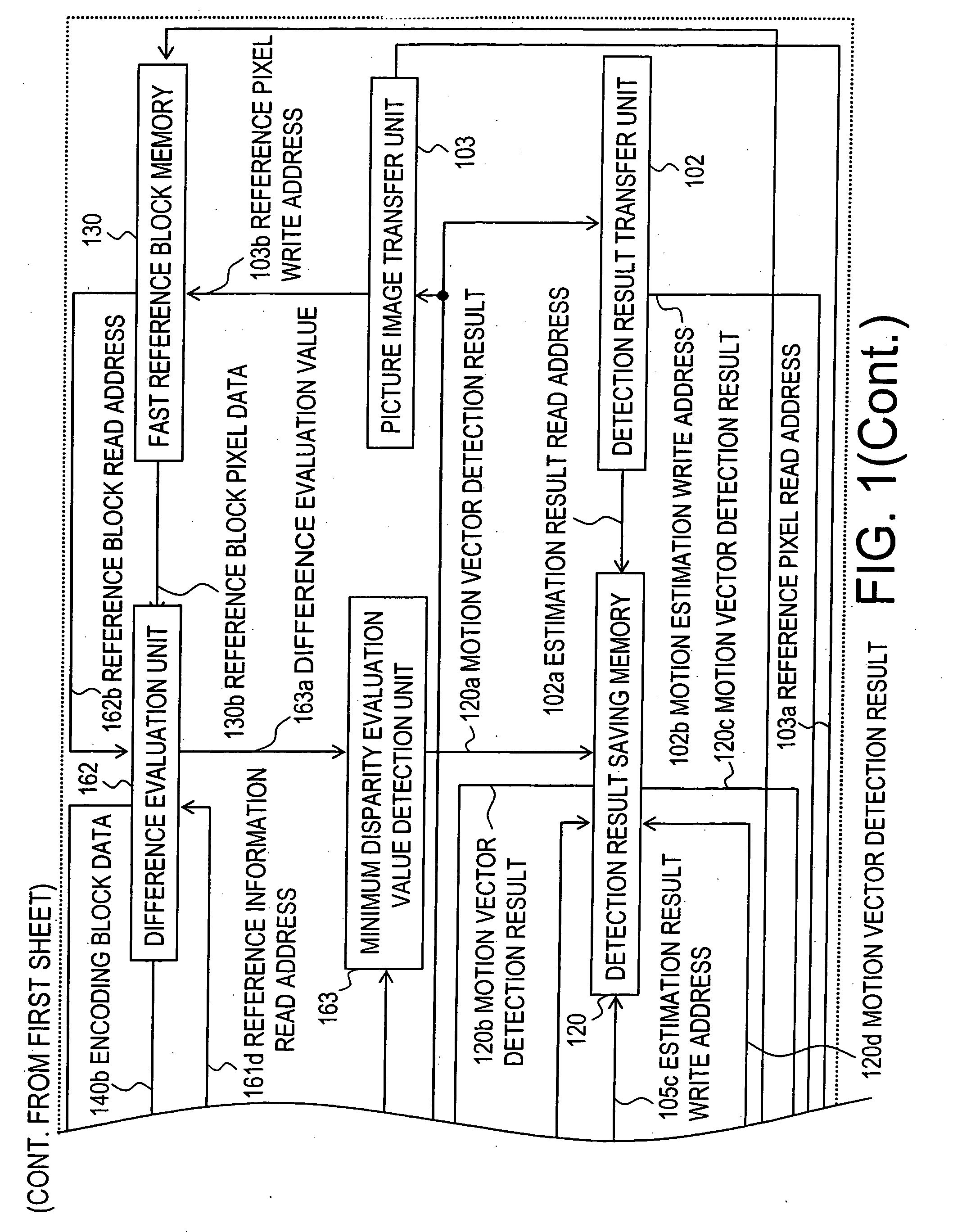
[0053]FIG. 1 illustrates a motion vector detector according to a first embodiment. The motion vector detector 10 is applied to a moving image encoding system using motion compensated prediction.

[0054]FIG. 2 is a block diagram showing a first specific example of an MPEG encoder comprising the motion vector detector 10 of the invention.

[0055]FIG. 3 is a block diagram showing a second specific example of an MPEG encoder comprising the motion vector detector 10 of the invention.

[0056] More specifically, the MPEG encoder shown in FIGS. 2 and 3 is a moving image encoder that compresses the amount of information using motion estimation information obtained by the motion vector detector 10 shown in FIG. 1.

[0057] First, these MPEG encoders are described. As shown in FIGS. 2 and 3, the MPEG encoder comprises an input image memory 910, aME (Motion Estimation) unit 10, aMC (Motion Compensation) unit 920, a DCT (Discrete Cosine Transform) unit 925, a quantization unit 930, an encoding / multip...

second embodiment

[0117] In the first embodiment, motion estimation per frame as shown in FIGS. 4 and 5 was illustrated. In the second embodiment, in the motion vector detector shown in FIG. 1, motion estimation per field as shown in FIGS. 27 and 28 will be illustrated.

[0118] The input image data 110a is written and saved at a location in the external large capacity memory 110, the location being indicated by an input image write address 101a generated by the image storing address generation unit 101.

[0119] First, the reference picture storage mode configuration unit 100 determines whether the picture to be encoded is a bidirectional prediction encoding picture (B-picture) that is allowed to use motion vectors from both of temporally past and future pictures in the display sequence. On the basis of the determination result, the reference picture storage mode configuration unit 100 generates a reference picture storage mode signal 100a that defines a reference pixel storage mode of the fast referenc...

third embodiment

[0213] As a third embodiment of the invention, image recording equipment comprising the motion vector detector according to the invention will now be described.

[0214]FIG. 29 is a block diagram showing a configuration of the image recording equipment according to the embodiment of the invention. More specifically, FIG. 29 illustrates image recording equipment having the capability of recording and reproducing various moving images including television (TV) broadcasts.

[0215] The image recording equipment 1000 comprises a recording / reproducing unit 1104 for recording video information of an inputted or received moving image on a given recording medium and reproducing compressed video information that has already been recorded according to a user's direction for reproduction. The image recording equipment 1000 also comprises a main controller 1105 implemented by a microprocessor (MPU) for controlling the operation of recording to and reproducing from the recording / reproducing unit 110...


PUM


Abstract

A motion vector detector that divides a picture which is encoded into a plurality of encoding blocks and evaluates differences between each encoding block and a reference block in a motion estimation range defined in a reference picture to detect a motion vector between pictures of a moving image.

Description

CROSS-REFERENCE TO RELATED APPLICATIONS [0001] This application is based upon and claims the benefit of priority from the prior Japanese Patent Application No. 2 003-296849, filed on Aug. 20, 2003; the entire contents of which are incorporated herein by reference. BACKGROUND OF THE INVENTION [0002] The invention relates to a motion vector detector and a method of detecting a motion vector for estimating motion between pictures of a moving image, wherein the motion estimation is required in a moving image encoder that uses MPEG or other motion compensated prediction schemes. [0003] One of the international standards of technologies for compressing moving images is the technology of encoding moving images based on the MPEG (Moving Picture Experts Group) standards, hereinafter referred to as MPEG encoding. [0004] The MPEG encoding requires detecting the motion between pictures of a moving image to generate a motion vector for motion compensated prediction. In this context, one method o...

Claims


Application Information

Patent Timeline
IPC IPC(8): H04N5/14H04N19/50H04N7/12H04N19/105H04N19/136H04N19/139H04N19/159H04N19/167H04N19/196H04N19/42H04N19/423H04N19/503H04N19/51H04N19/57H04N19/577
CPCH04N5/145H04N19/51H04N19/105H04N19/112H04N19/423H04N19/61H04N19/43H04N19/156
Inventor UETANI, YOSHIHARU
Owner KK TOSHIBA
Why Eureka
Try Eureka