Sound distortion feedback

a feedback and sound technology, applied in the field of sound distortion feedback, can solve the problems of not knowing he will not know on which side of the range he is performing, and the user will not know how far he is from the desired range, so as to reduce or eliminate certain frequency ranges

Inactive Publication Date: 2011-10-20
LAERDAL MEDICAL AS
View PDF2 Cites 3 Cited by
  • Summary
  • Abstract
  • Description
  • Claims
  • Application Information

AI Technical Summary

Benefits of technology

The invention relates to an audio playback system which can adjust its output based on different parameters such as volume level or genre preference. One feature allows for playing back music while keeping it at a specific pitch (frequency) level. If the music has too many high-pitched notes, the system will use a special filter to reduce those notes. This results in a cleaner sounding version of the music without distortion.

Problems solved by technology

The technical problem addressed by this patent is the lack of effective feedback for rescuers performing cardiopulmonary resuscitation (CPR) procedures. Existing devices provide only limited guidance through auditory cues, resulting in difficulty in accurately assessing the quality of CPR performances. There is a need for improved feedback systems that allow rescuers to easily identify areas where their actions fall below or exceed the required standards.

Method used


Image

  • Sound distortion feedback
  • Sound distortion feedback
  • Sound distortion feedback

Examples


first embodiment

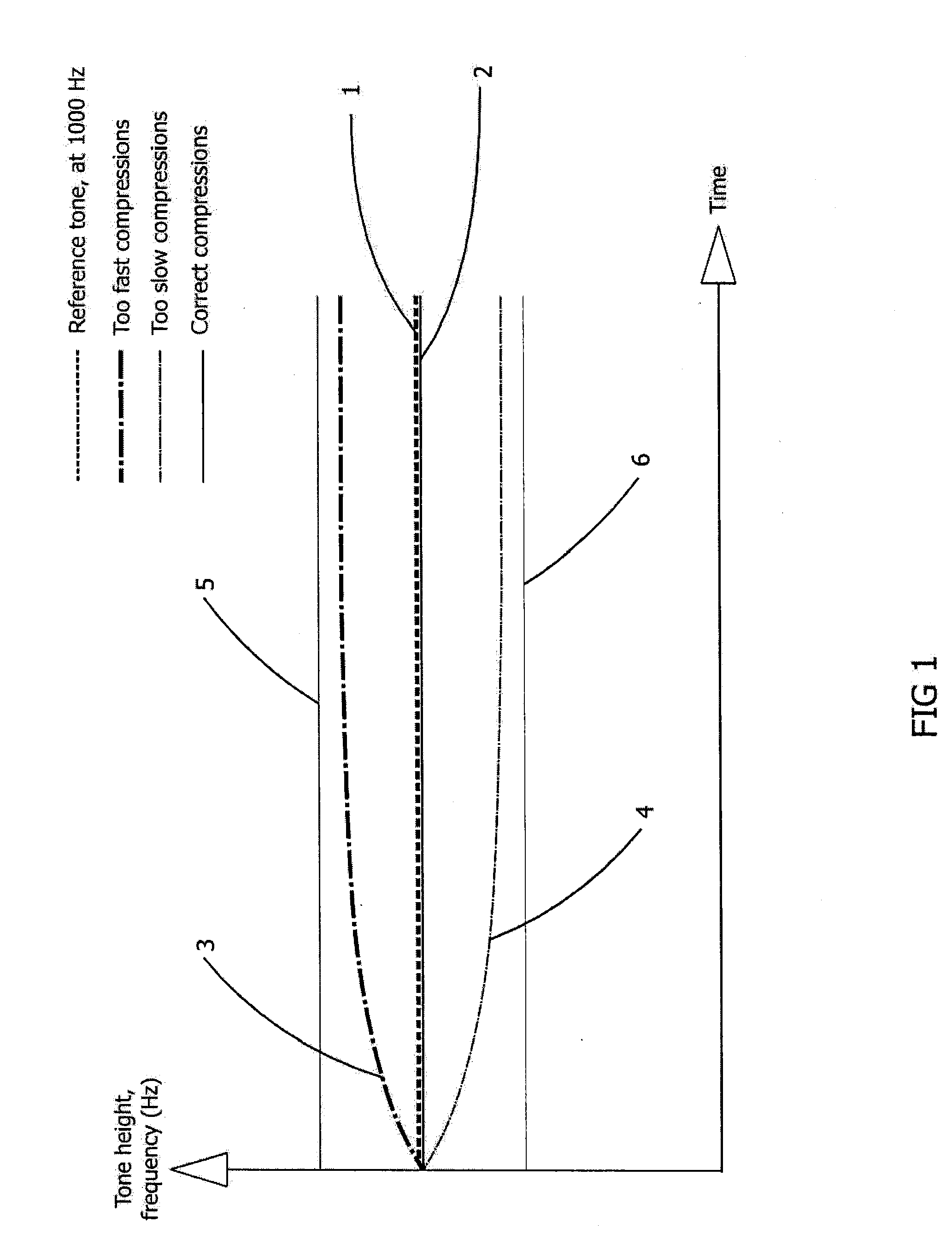
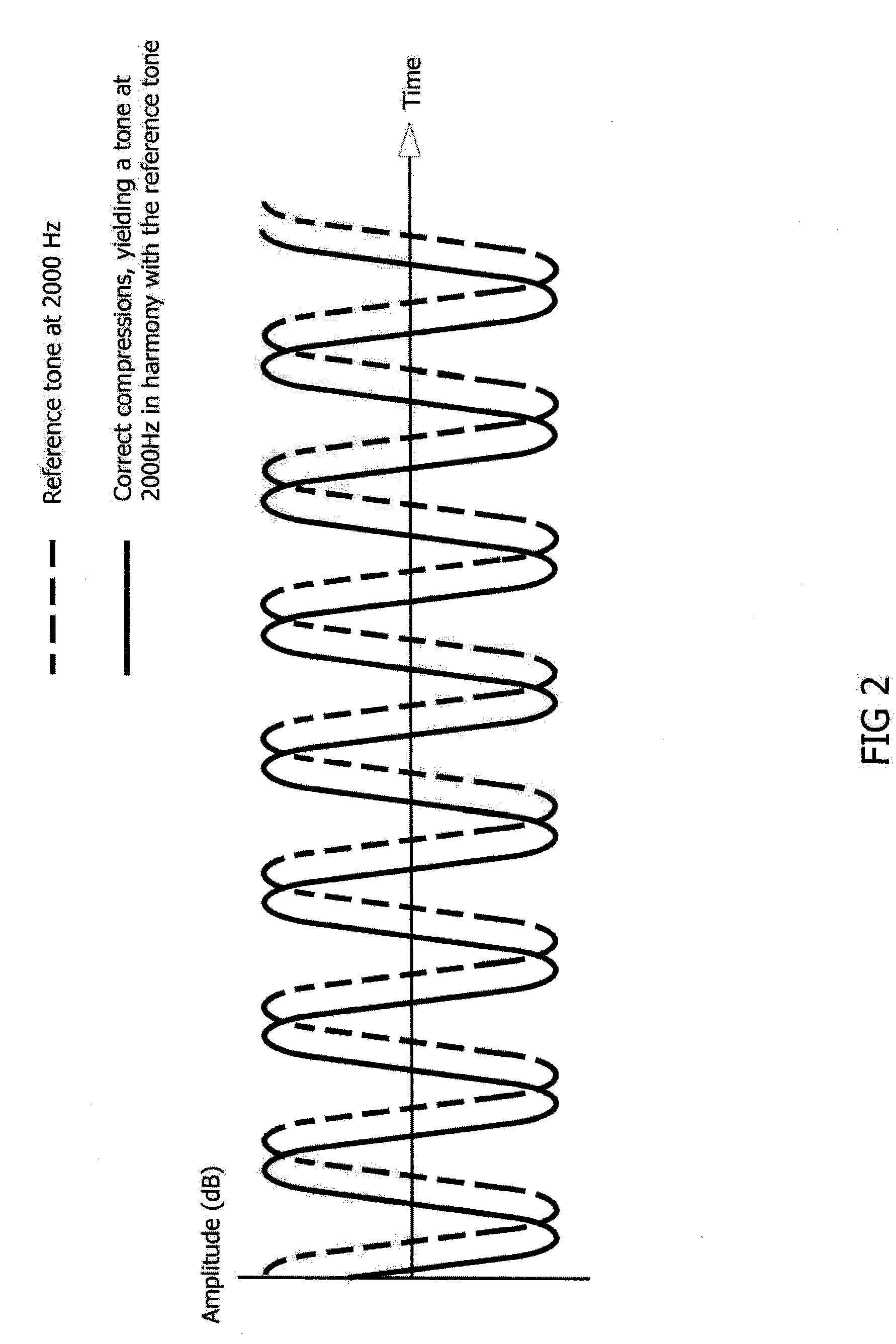
[0026]Therefore the present invention uses two tones only. A reference tone 1, which is played with a constant pitch, and a variable tone, with a pitch that can vary. The frequency of the varying tone is based on the speed of the compressions. When the rescuer compresses at the desired rate, the constant tone 1 and the varying tone 2 will have the same pitch. The two tones will be perceived as one tone only.

[0027]When the rescuer compresses faster than desired, the varying tone will be played with a higher pitch 3 than the constant tone. The faster the rescuer compresses, the higher the pitch will be.

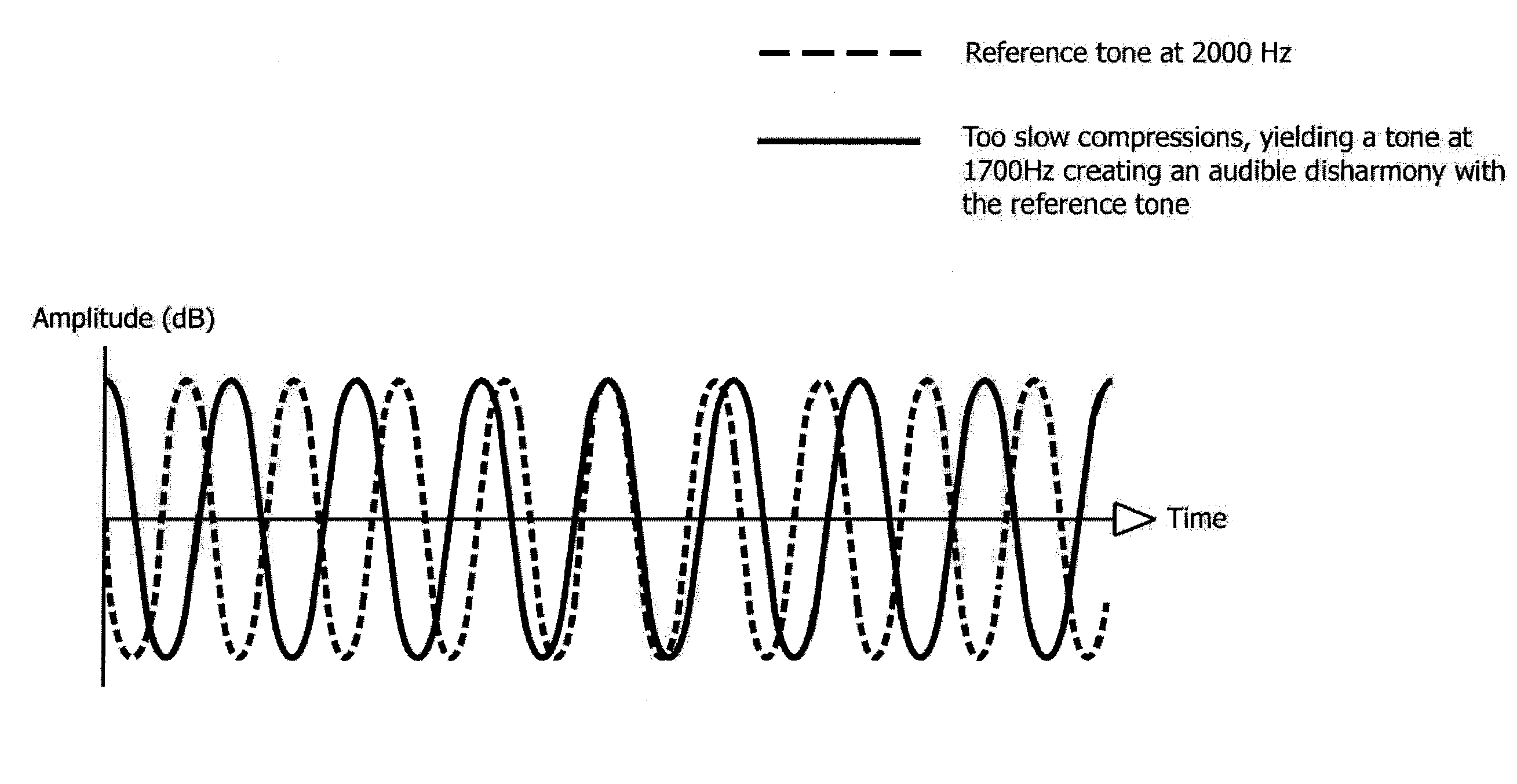
[0028]However, the pitch of the varying tone 3 will always lie between the constant tone 1 and the closest higher harmonic 5 of that tone. Thereby the varying tone will be in dissonance with the constant tone. The rescuer will perceive these superimposed tones 1, 3 as unpleasant or at least to have a richer sound picture than the single tone 1, 2 played when the compression rate is corr...

second embodiment

[0033]In the present invention a piece of music is used. In the beginning, and as long as the compression rate is correct, the music is played back at the correct speed. The musical piece can be chosen to have a beat coinciding with the desired compression rate when played back at the correct speed.

[0034]In order to indicate to the rescuer that he or she compresses with an incorrect rate, the speed of the playback can be altered. This can be done by altering the sampling rate.

[0035]A digital sound signal is commonly defined with a reference frequency, as a property of the file format, and this defines the number of sample points or recorded positions of an air molecule pr. second. This can typically be 44.1 kHz, and means that the position of the vibrating air molecule has been recorded 44100 times pr. second. The number of times the air molecule reaches its extreme positions pr second is what defines the pitch or frequency of the recorded sound. If a sound is recorded with a sample...


PUM


Abstract

A system is described for facilitating correct performance of CPR by providing feedback to a person performing chest compressions during basic life support or CPR training. The device is adapted to give audio signals to the user indicative of chest compressions being within a desired range or being outside of the desired range. In a first aspect the audio signal comprises two tones, a first tone that is substantially constant in pitch and a second tone that has a varying pitch. The pitch of the second tone is varying in response to a parameter of the chest compression performance. When the parameter is within a desired range, the second tone has substantially the same pitch as the first tone and when the parameter is outside the desired range, the pitch of the second tone is different from the first tone. In a second aspect the audio signal is a piece of music. This is played back at normal speed when a parameter of the chest compression performance is within a desired range and played back at a different speed when the parameter is outside off the desired range. In a third aspect the piece of music is played back with a normal range of frequencies when the parameter is within the desired range. If the parameter is outside the desired range the piece of music is played back using a cut off filter that reduces or eliminates certain frequency ranges of the piece of music.

Description


Claims


Application Information

Patent Timeline
Owner LAERDAL MEDICAL AS
Why Eureka
Try Eureka