Tape measure with self-regulating speed control mechanism

Inactive Publication Date: 2011-10-27
KOMELON
View PDF7 Cites 2 Cited by
  • Summary
  • Abstract
  • Description
  • Claims
  • Application Information

AI Technical Summary

Benefits of technology

[0008]Accordingly, the present invention has been made keeping in mind the above problems occurring in the prior art, and an object of the present invention is to provide a tape measure with a self-regulating speed control mechanism by which the speed at which a blade is retracted into a casing can be self-controlled and maintained at an appropriate speed such that it is prevented from being excessively fast or slow, and which can prevent noise from occurring when the blade is retracted.
[0009]In order to accomplish the above object, the present invention provides a tape measure in which when a bobbin rotates, a rubber roller rotatably provided on a movable mounting plate alternately comes into contact with an inner surface of a support ring and a rubber acceleration prevention member provided on the inner surface of the support ring, so that the speed of the bobbin can be smoothly and reliably reduced.

Problems solved by technology

Therefore, if the portion of the blade that is extracted from the casing is very long, the acceleration of the blade which is being retracted into the casing is excessively increased.
Thus, a user who is using the tape measure or nearby people may be injured or the tape measure itself may be damaged.

Method used


Image

  • Tape measure with self-regulating speed control mechanism
  • Tape measure with self-regulating speed control mechanism
  • Tape measure with self-regulating speed control mechanism

Examples


experimental example a

[0058]In this example, a stationary hard plastic brake is provided on each movable mounting plate. In other words, this case is configured in such a way that the hard plastic brake is fastened to the movable mounting plate without having a structure like the roller and is brought into the support ring or the like to reduce the rotational speed of the bobbin.

experimental example b

[0059]In this example, a stationary soft rubber brake is provided on each movable mounting plate. That is, this case is configured in such a way that the soft rubber brake is fastened to the movable mounting plate without having a structure like the roller and is brought into the support ring or the like to reduce the rotational speed of the bobbin.

experimental example c

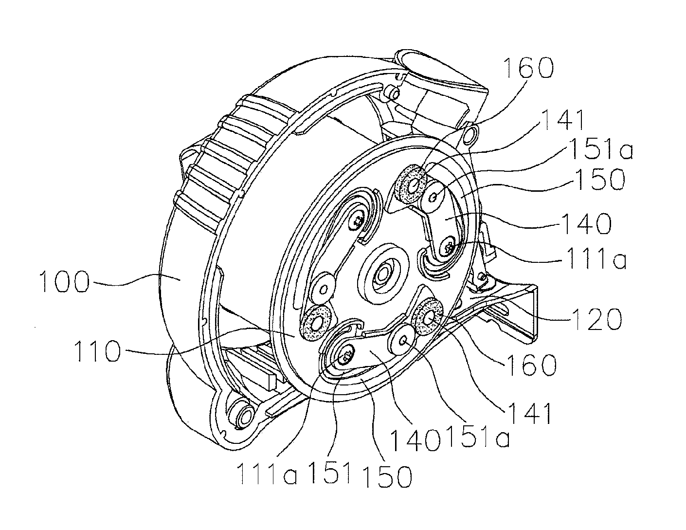
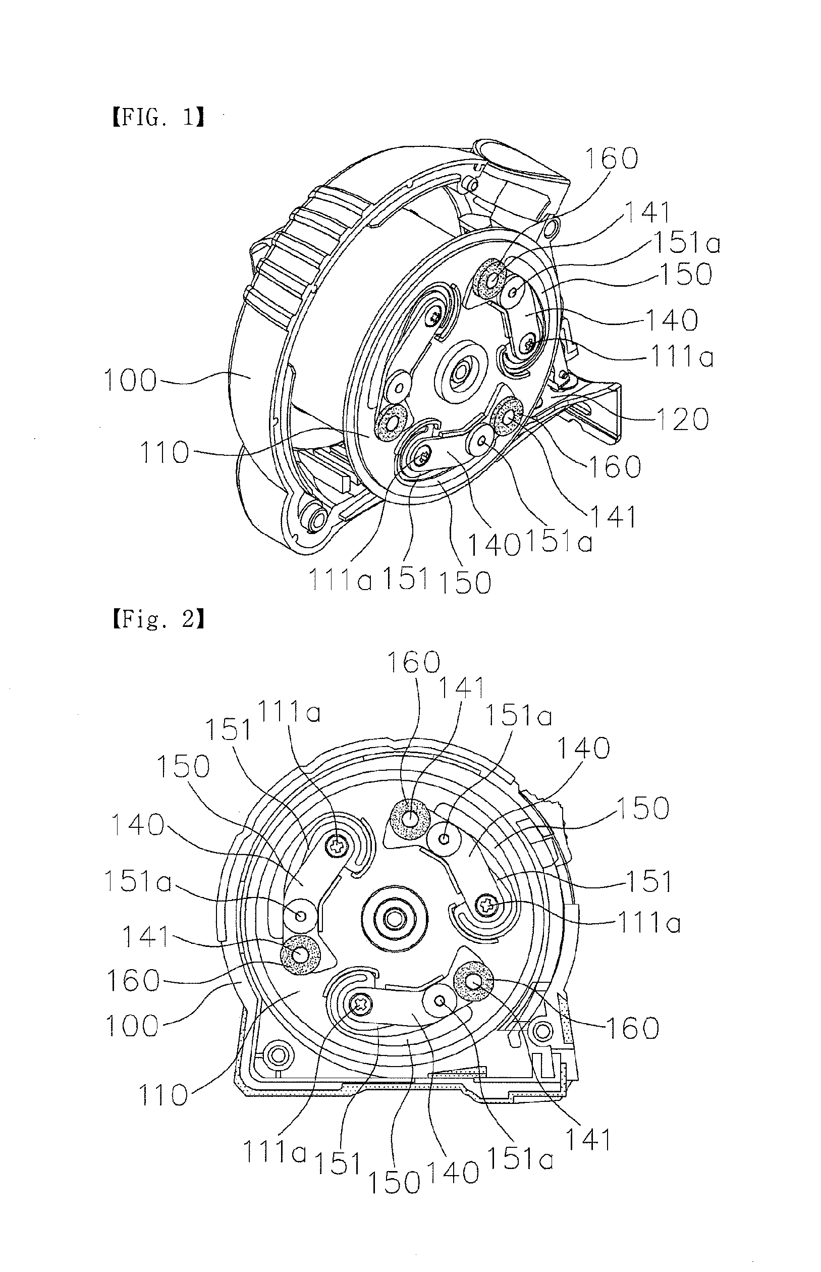
[0060]In this example, a rubber roller is rotatably provided on each movable mounting plate. That is, in this case, the roller of the embodiment of the present invention (the roller having the same structure as that of FIG. 2) is mounted to the movable mounting plate.

Experimental Example {circle around (a)}

[0061]This example is a case in which only support ring is provided on the casing. In this case, the support ring has no acceleration prevention member and is made of hard plastic.

Experimental Example {circle around (b)}

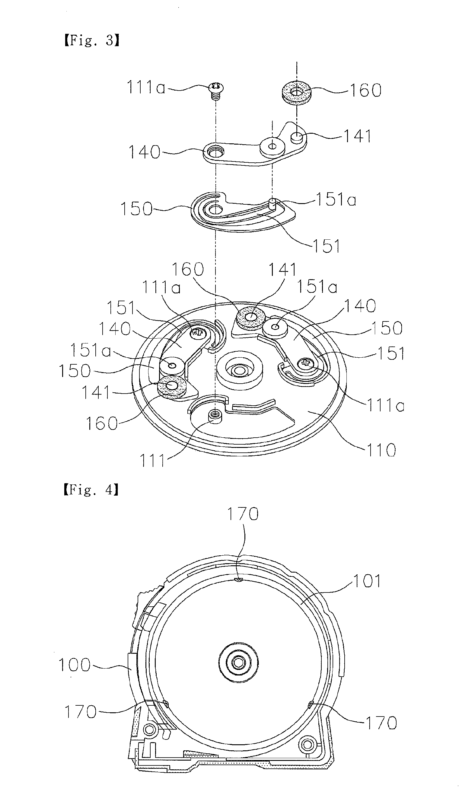
[0062]This example is a case in which acceleration prevention members made of hard plastic are provided on the support ring. In this case, the acceleration prevention members have the same shape and arrangement as those of the acceleration prevention members of FIG. 4, but the material thereof is made of hard plastic unlike the case of FIG. 4 that is made of rubber.

Experimental Example {circle around (c)}

[0063]This example is a case in which acceleration prevention...


PUM


Abstract

Disclosed herein is a tape measure with a self-regulating speed control mechanism. In the present invention, when a bobbin rotates, a rubber roller rotatably provided on a movable mounting plate alternately comes into contact with an inner surface of a support ring and a rubber acceleration prevention member provided on the inner surface of the support ring, so that the speed of the bobbin can be smoothly and reliably reduced.

Description

BACKGROUND OF THE INVENTION[0001]1. Field of the Invention[0002]The present invention relates generally to tape measures and, more particularly, to a tape measure with a self-regulating speed control mechanism by which when a blade that has been extracted from a casing is retracted into the casing, the retraction speed of the blade is self-controlled such that a predetermined speed is maintained.[0003]2. Description of the Related Art[0004]Generally, a tape measure includes a casing in which a bobbin is rotatably provided. One end of a blade (referred to simply as a “tape”) is wound around the bobbin, and the other end thereof protrudes out of the casing. The end of the blade that protrudes out of the casing is pulled and extracted and then used to make a variety of measurements.[0005]To rewind the blade around the bobbin again after the measurements have been completed, a first elastic member is coupled to the bobbin and provides elastic rotating force to the bobbin. A plate spring...

Claims


Application Information

Patent Timeline
IPC IPC(8): G01B3/10
CPCG01B2003/102G01B3/1005G01B3/102
Inventor KANG, DONG HUN
Owner KOMELON
Why Eureka
Try Eureka