Warm-up bat

a warm-up bat and bat body technology, applied in the field of warm-up bats, can solve the problems of not including a bat which provides the weight, balance, performance and performance of a standard game bat in these techniques and devices

Inactive Publication Date: 2006-12-12
NUTTER SPORTS L L C
View PDF39 Cites 69 Cited by
  • Summary
  • Abstract
  • Description
  • Claims
  • Application Information

AI Technical Summary

Benefits of technology

[0040]Another example of sliding weight mechanism includes a tapered end plug, a bolt, a spring, a magnet, and a sliding weight with bushings. The tapered end plug includes a centrally positioned aperture configured for enabling the bolt to be passed therethrough. The spring is configured to inhibit the noise that may occur when the sliding weight moves from a position proximate the end cap and return to a position near the magnet.
[0042]As the swinging motion causes the warm-up bat to increase speed, the magnetic force on the sliding weight is overcome, allowing the sliding weight to slide on the shaft. The player feels the corresponding shift in mass as the swing progresses. When the sliding weight reaches the end of the shaft, at the end of the barrel section proximate the end cap, the sliding weight is dampened mechanically by the cylindrical portion of the end cap. Therefore, little or no sound is heard, but the player feels the impact of the sliding weight at the end of the bat.
[0043]A warm-up bat may be equipped with a sliding weight mechanism alternatively configured to include a tapered end plug, a die spring, fingers, a plate, a cushion, and a sliding weight with bushings. The sliding weight has a necked down feature, enabling it to be held by the spring loaded fingers. These fingers are held in place on a plate, and allowed to pivot on pins. A die spring or similar spring forces the ends of the fingers open, thus keeping the sliding weight restrained by the closed end of the fingers. A cushion material prevents metal to metal contact between the sliding weight and the plate. With this sliding weight mechanism, the swing of the bat similarly causes the sliding weight to push away from the handle portion of the bat and toward the end cap of the bat, but the sliding weight is not released until sufficient force is generated to overcome the spring pressure on the fingers.

Problems solved by technology

However, none of these techniques and devices includes a bat which provides the weight, balance, and performance of a standard game bat, and does not include external attachments, and does not have an irregular shape.

Method used


Image

  • Warm-up bat
  • Warm-up bat
  • Warm-up bat

Examples


Embodiment Construction

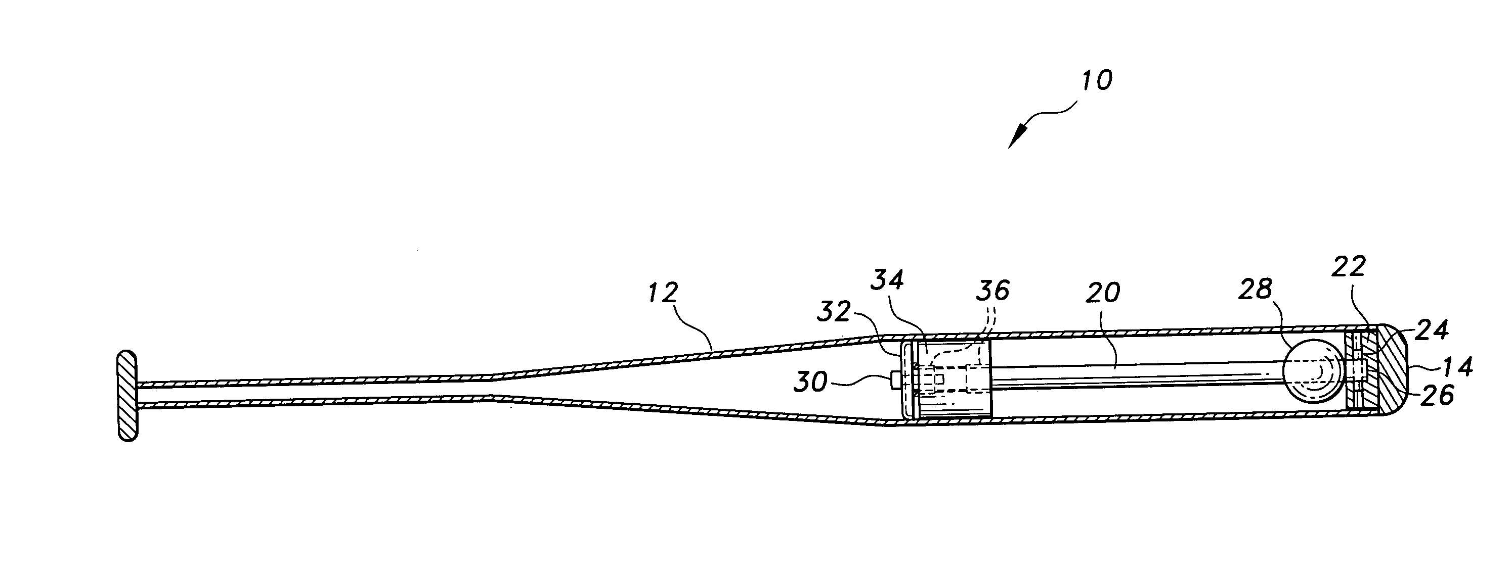
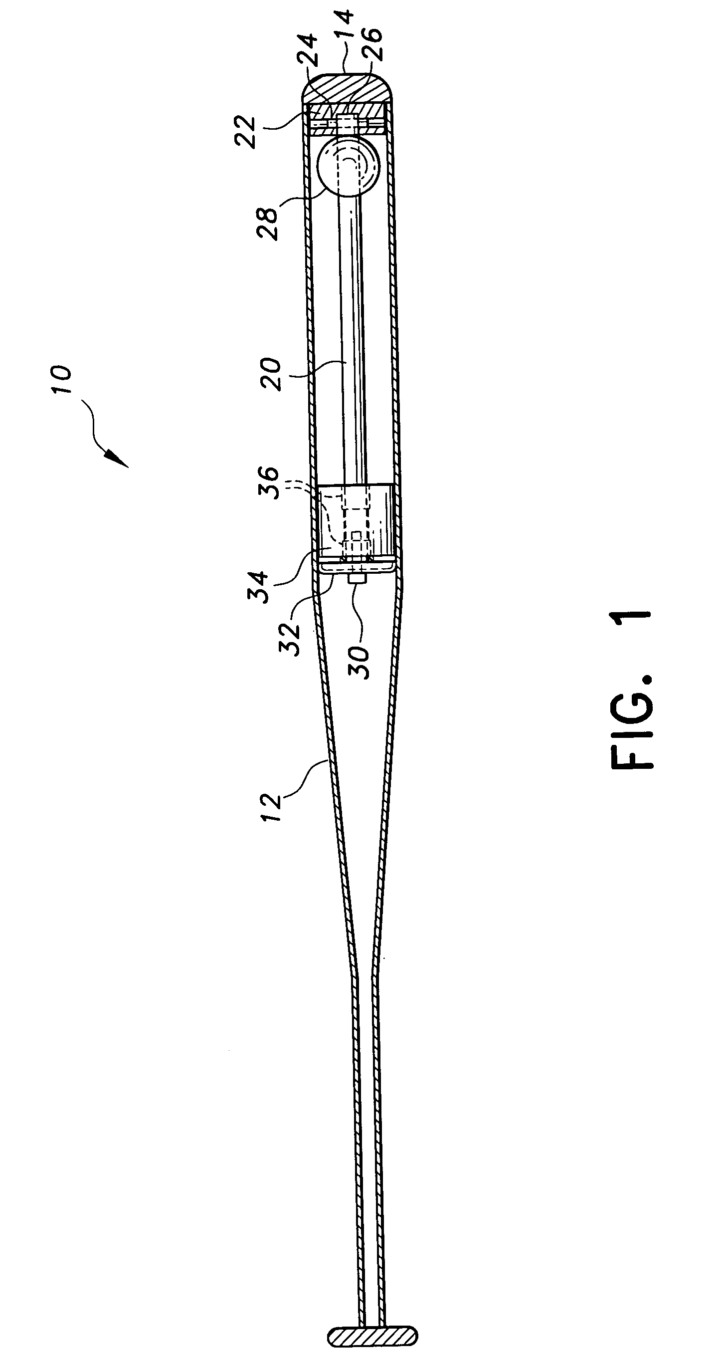
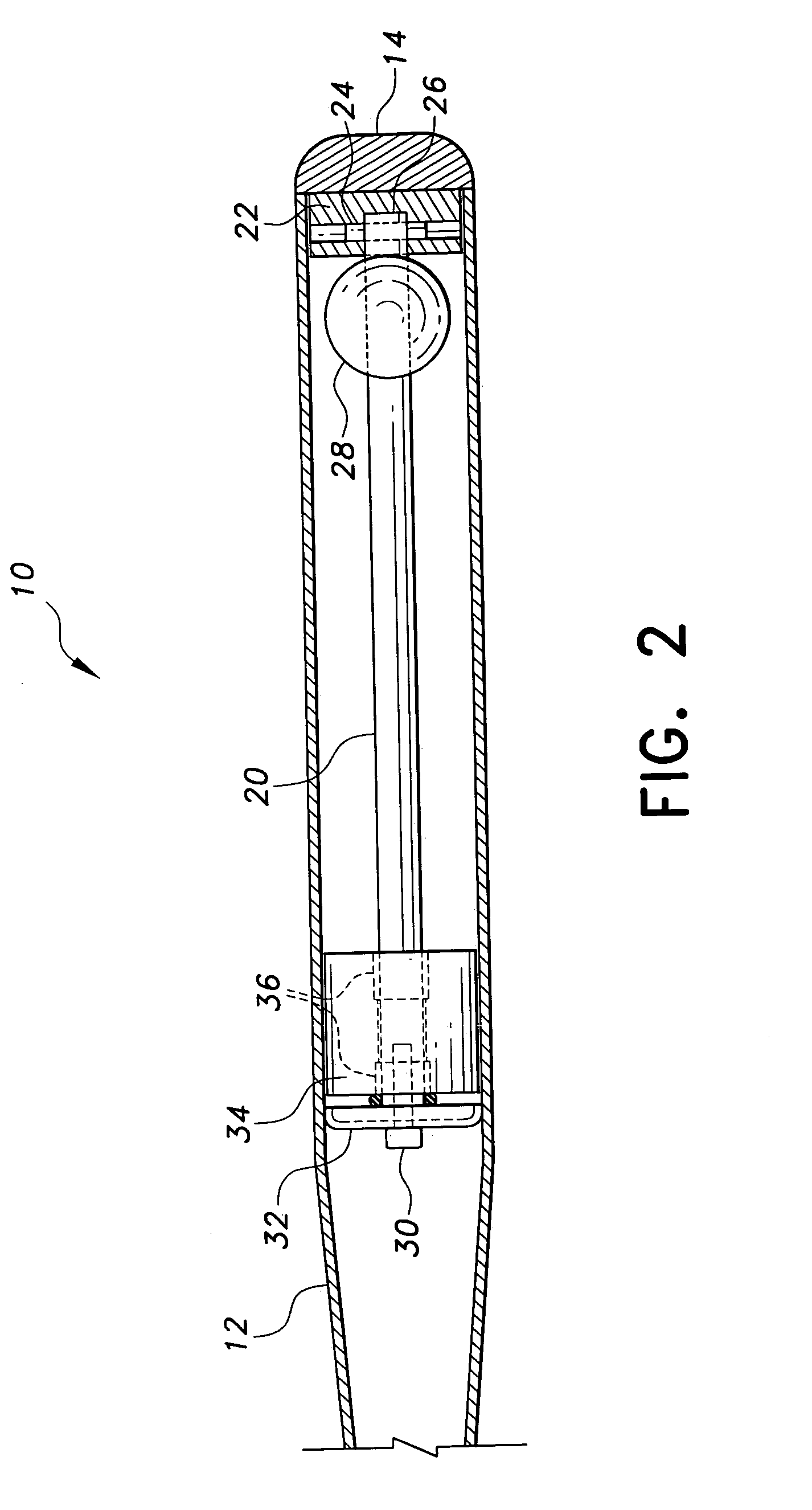
[0051]The present invention is a warm-up bat. The invention disclosed herein is, of course, susceptible of embodiment in many different forms. Shown in the drawings and described herein below in detail are preferred embodiments of the invention. It is to be understood, however, that the present disclosure is an exemplification of the principles of the invention and does not limit the invention to the illustrated embodiments.

[0052]Referring to the drawings, FIGS. 1 and 2 show one example of a warm-up bat 10 according to the invention. The warm-up bat 10 includes a tubular shell 12, a handle, and an end cap 14. The tubular shell 12 is made of metal, metal alloy, or a metal composite, such as aluminum, titanium, steel, titanium aluminum alloys, titanium alloys, nickel alloys, metal matrix composite alloys, combinations thereof, or the like. The tubular shell 12 includes a handle section, a barrel section, and a tapered section connecting the handle section with the barrel section. The ...


PUM


Abstract

A warm-up bat includes a tubular shell with a handle section, a barrel section, and a tapered section connecting the handle section with the barrel section. The handle is attached at an end of the handle section of the bat. An end cap is attached at an end of the barrel section of the bat. A sliding weight mechanism is entirely contained within the barrel section of the bat, and is positionally supported on a shaft.

Description

CROSS-REFERENCE TO RELATED APPLICATION[0001]This application claims the benefit of U.S. Provisional Patent Application Ser. No. 60 / 535,546, filed Jan. 12, 2004, which is incorporated herein by reference.BACKGROUND OF THE INVENTION[0002]1. Field of the Invention[0003]The present invention generally relates to exercising and training for baseball and softball and, more particularly, to a warm-up bat that incorporates a sliding weight mechanism inside the barrel of a metallic or composite hard shell bat.[0004]2. Description of Related Art[0005]When a baseball or softball player attempts to hit a baseball or softball during a game, the player initially takes a standing position at the plate and holds a bat in a rearward cocked position. Once the pitch is thrown, the player swings the bat from the laterally rearward cocked position, through a frontal hitting position, and to a follow-through laterally forward position. The player swings the bat at an appropriate time after the pitcher fa...

Claims


Application Information

Patent Timeline
Patent Type & Authority Patents(United States)
IPC IPC(8): A63B69/00A63B15/00A63B59/06
CPCA63B15/005A63B24/0062A63B69/0002A63B2024/0068A63B2069/0008A63B2209/08A63B2220/51A63B60/50
Inventor NUTTER, MARK E.MARON, ROBERT A.NUTTER, JACOB
Owner NUTTER SPORTS L L C
Why Eureka
Try Eureka