Hinge-slide cover mounting structure using a sheet metal bracket mechanism

a technology of mounting structure and slide cover, which is applied in the direction of manufacturing tools, instruments, portable computers, etc., can solve the problems of increasing the weight of the slide cover mounting structure, lcd display panel may be erroneously biased from position, and not allowing smooth lifting of the lcd display panel, etc., to achieve the effect of minimizing the weigh

Active Publication Date: 2012-09-25
LIANHONG TECH
View PDF21 Cites 69 Cited by
  • Summary
  • Abstract
  • Description
  • Claims
  • Application Information

AI Technical Summary

Benefits of technology

[0010]The present invention has been accomplished under the circumstances in view. It is one object of the present invention to provide a liftable slide cover mounting structure, which uses sheet plate bracket mechanisms to hold sliding rails instead of zinc alloy sliding rail holders, thereby minimizing the weight.
[0011]It is another object of the present invention to provide a liftable slide cover mounting structure, which has elongated plastic sliding blocks arranged on sheet plate bracket mechanisms to support metal sliding rails, avoiding noises during sliding motion of the metal sliding rails.
[0012]It is another object of the present invention to provide a liftable slide cover mounting structure, which has the common gear shaft of two gears pivotally connected between the sheet plate bracket mechanisms so that the gears are constantly kept in mesh with respective gear racks when opening the cover panel from the base member of the electronic device in which the liftable slide cover mounting structure is installed, enabling the applied force to be distributed to the two opposite lateral sides evenly, avoiding biasing and assuring smooth movement of the cover panel relative to the base member.
[0013]It is another object of the present invention to provide a liftable slide cover mounting structure, which uses supplementary support mechanisms to support the hinges on the base member of the electronic device so that when the cover panel is opened from the base member, the sheet plate bracket mechanisms are forced into engagement with the supplementary support mechanisms to support the cover panel in position for enabling the user to operate the display screen of the cover panel positively.
[0014]To achieve these and other objects of the present invention, a liftable slide cover mounting structure is used in an electronic device comprising a cover panel and a base member. The liftable slide cover mounting structure comprises two hinges respectively fixedly mounted on a middle part of a top wall of the base member adjacent to two opposite lateral sides thereof, each hinge comprising a rotatable pivot shaft; two sheet plate bracket mechanisms respectively connected to the pivot shafts of the hinges and rotatable upwardly relative to the base member, each sheet plate bracket mechanism comprising a pair of elongated plastic sliding blocks, each elongated plastic sliding block defining a longitudinal sliding groove; two sliding rails bilaterally fixedly mounted on a bottom surface of the cover panel in a parallel manner and respectively slidably coupled to the longitudinal sliding grooves of the elongated plastic sliding blocks of one sheet plate bracket mechanism; a gear shaft pivotally connected between the sheet plate bracket mechanisms; two gears respectively fixedly mounted on the fixed gear shaft adjacent to the sheet plate bracket mechanisms; and two gear racks respectively mounted on the bottom surface of the cover panel in a parallel manner and respectively meshed with the gears. When the cover panel slides forwards relative to the base member to move the sliding rails in the longitudinal sliding grooves of the elongated plastic sliding blocks of the sheet plate bracket mechanisms when receiving a horizontal push force, and at the same time, the gear racks are forced to rotate the gears for enabling the received horizontal push force to be evenly transferred through the gear shafts to the two opposite lateral sides of the base member, avoiding biasing of the cover panel; the gears are kept meshed with the gear racks constantly for enabling the cover panel to be turned about the pivot shafts of the hinges from a horizontal position to a tilted position relative to the base member.

Problems solved by technology

However, this design does not allow smooth lifting of the LCD display panel.
Because the gear is not constantly kept in mesh with the gear rack, the LCD display panel may be erroneously biased from position.
However, the sliding rail holders are made of zinc alloy, increasing the weight of the slide cover mounting structure.
Further, the metal sliding rail holders are kept in contact with the metal sliding rails to cause noises during movement of the metal sliding rails.

Method used


Image

  • Hinge-slide cover mounting structure using a sheet metal bracket mechanism
  • Hinge-slide cover mounting structure using a sheet metal bracket mechanism
  • Hinge-slide cover mounting structure using a sheet metal bracket mechanism

Examples


Embodiment Construction

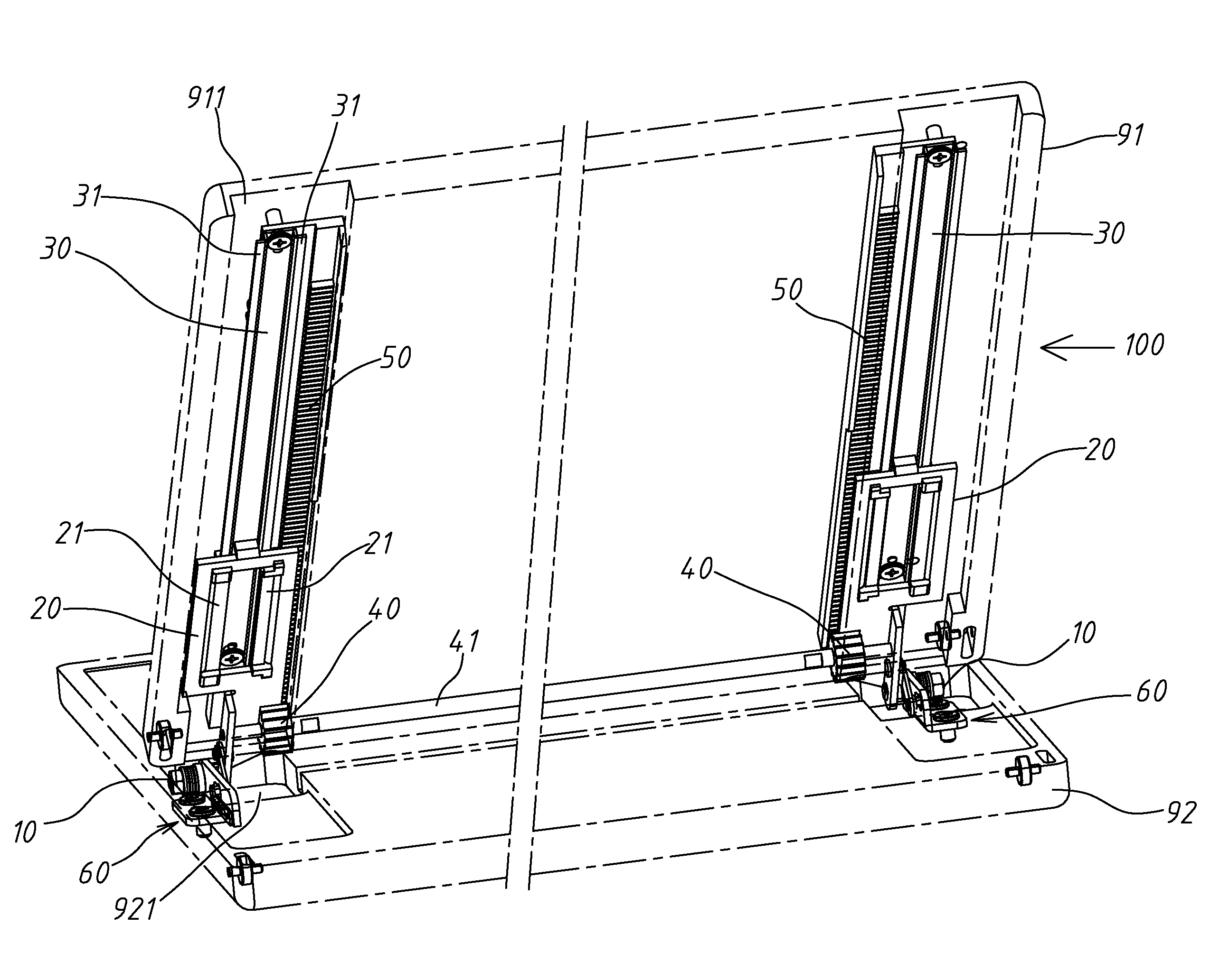
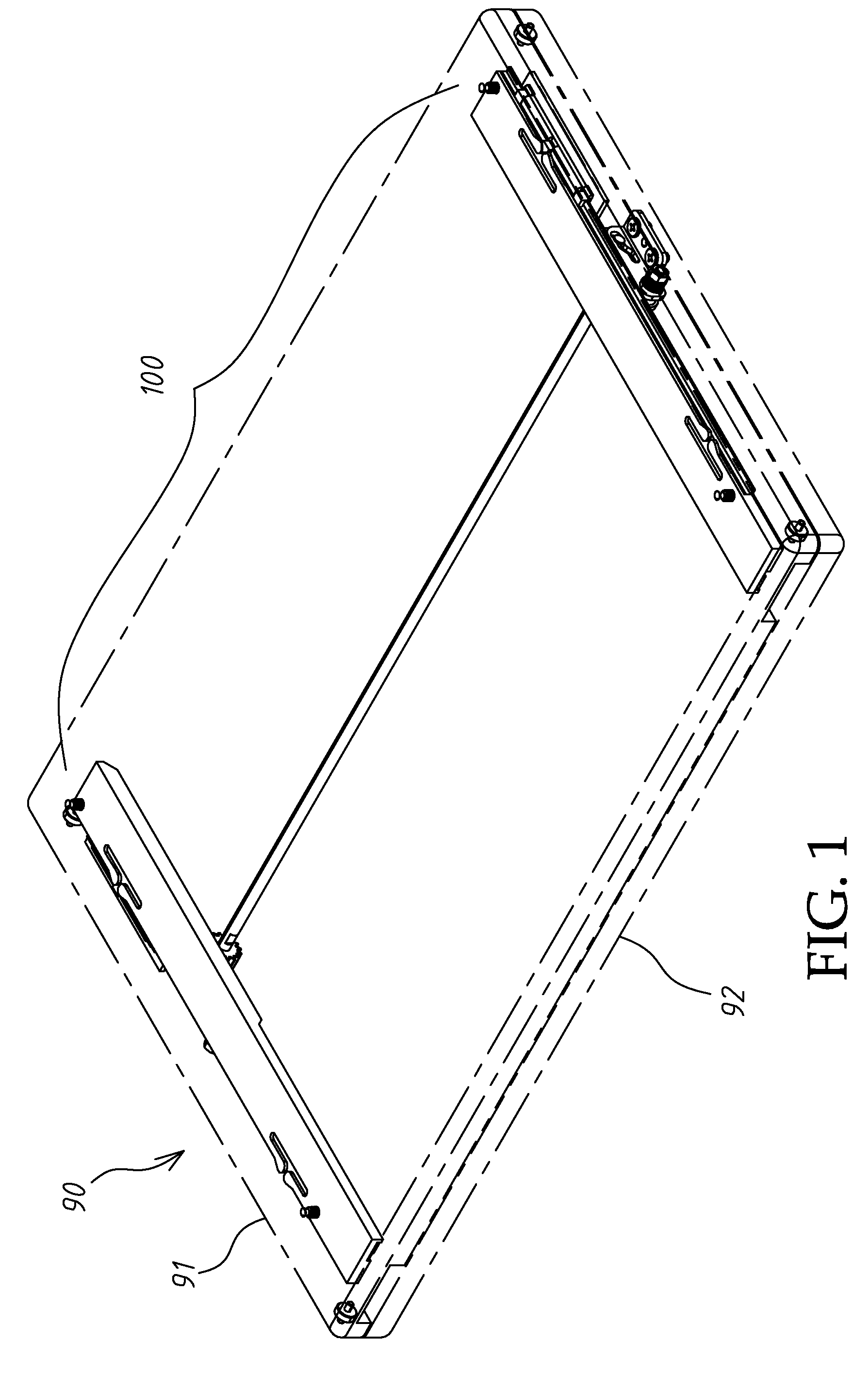
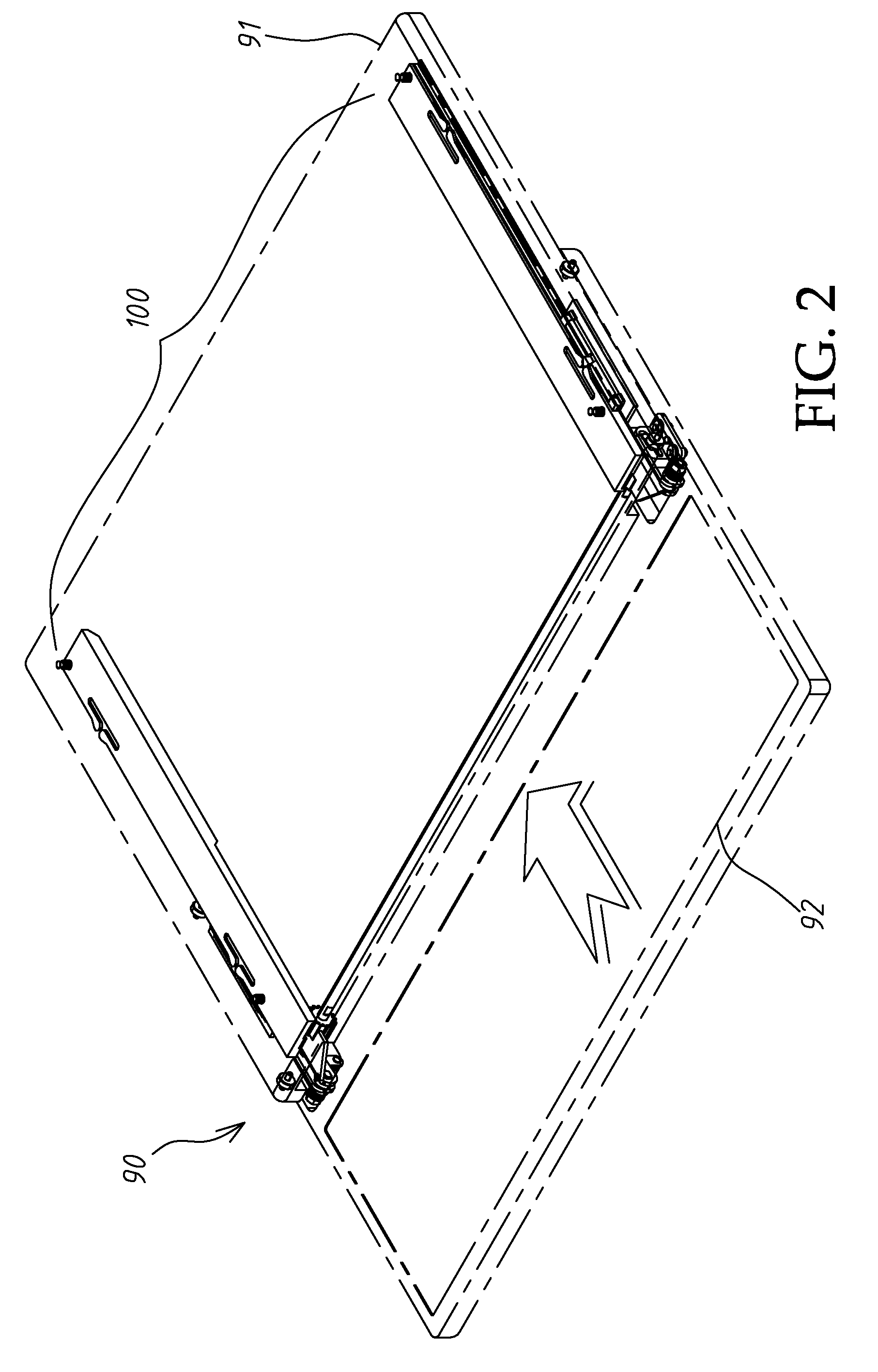
[0023]Referring to FIGS. 1˜3, a liftable slide cover mounting structure 100 in accordance with the present invention is shown used in an electronic device 90 comprising a cover panel 91 and a base member 92. The electronic device 90 can be, for example, a tablet computer. The cover panel 91 is a LCD display panel. The base member 92 is the operating system end of the electronic device 90, comprising a keyboard. When going to open the cover panel 91, slide the cover panel 91 on the base member 92 (see FIG. 2) and then lift the cover panel 91 from the base member 92 to a tilted position (see FIG. 3).

[0024]Referring to FIG. 4, the liftable slide cover mounting structure 100 comprises a pair hinges 10, a pair of sheet plate bracket mechanisms 20, a pair of sliding rails 30, a pair of gears 40, a pair of gear racks 50 and a pair of supplementary support mechanisms 60.

[0025]Referring also to FIG. 5, the hinges 10 are respectively arranged on the supplementary support mechanisms 60 and res...


PUM


Abstract

A liftable slide cover mounting structure consisting of two hinges, two metal sheet bracket mechanism, two sliding rails, two gears, two gear racks and two supplementary support mechanisms. Subject to the use of the sheet plate bracket mechanisms to hold the sliding rails instead of zinc alloy sliding rail holders, the weight of the liftable slide cover mounting structure is minimized. Further, when the cover panel is opened from the base member, the sheet plate bracket mechanisms are forced into engagement with the supplementary support mechanisms to support the cover panel in position for enabling the user to operate the display screen of the cover panel positively.

Description

BACKGROUND OF THE INVENTION[0001]1. Field of the Invention[0002]The present invention relates to slide cover mounting technology and more particularly, to a liftable slide cover mounting structure for use in an electronic device, for example, tablet computer, which using a sheet metal bracket mechanism to hold sliding rails instead of zinc alloy sliding rail holders, minimizing the weight.[0003]2. Description of the Related Art[0004]Following development and function improvement of touch control technology, tablet computer has become popular. The LCD screen of a tablet computer is located on the outer surface of the computer for convenient operation.[0005]However, the use of a keyboard is a common practice to most people for, for example, text word input. There are tablet computers that comprise an operating system end arranged at the bottom side of the LCD display panel. Thus, the LCD display panel can be moved horizontally relative to the operating system end and then lifted to a ...

Claims


Application Information

Patent Timeline
Patent Type & Authority Patents(United States)
IPC IPC(8): E05D7/00E05D3/06
CPCG06F1/1616G06F1/1624Y10T16/547Y10T16/541Y10T16/54025Y10T16/544
Inventor CHEN, CHIA HUILIN, CHE-HSIEN
Owner LIANHONG TECH
Why Eureka
Try Eureka