

Sparse Array RF Imaging for Surveillance Applications
a technology of rf imaging and surveillance applications, applied in the field of surveillance systems, can solve the problems of affecting the utility of captured images, and the cost of infrared imaging cameras often prohibiting the use of a large number of cameras
- Summary
- Abstract
- Description
- Claims
- Application Information
AI Technical Summary
Benefits of technology
Problems solved by technology
Method used
Image

Examples
Embodiment Construction
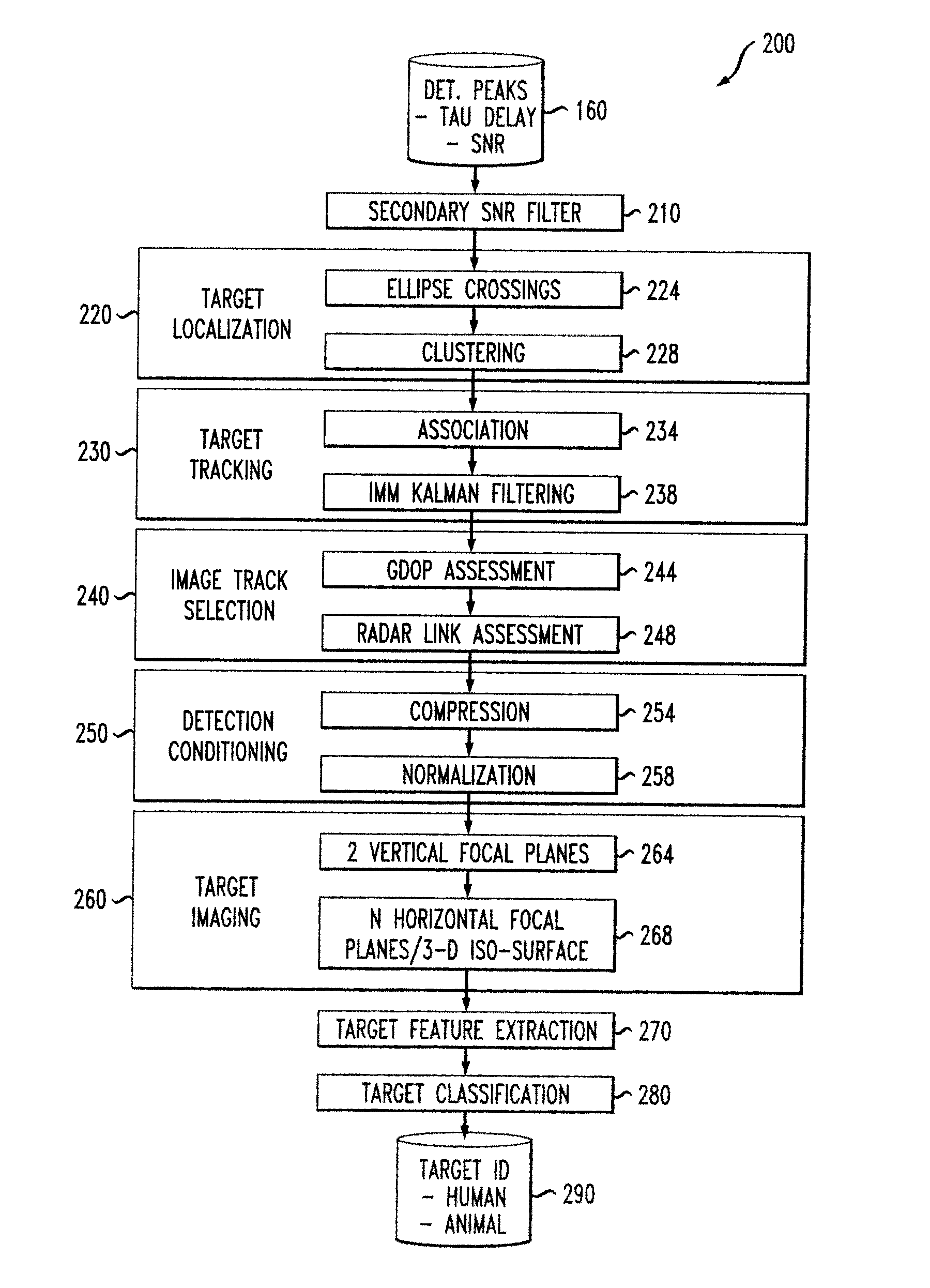
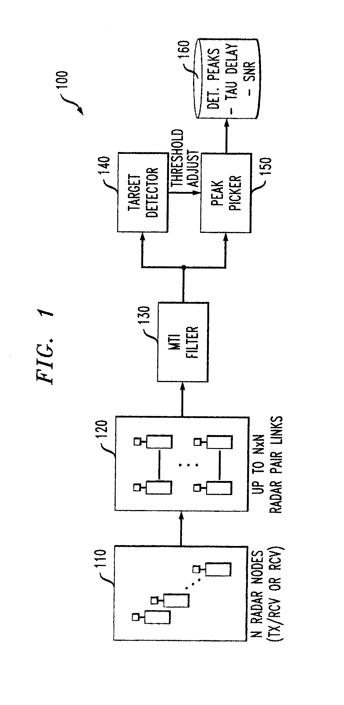
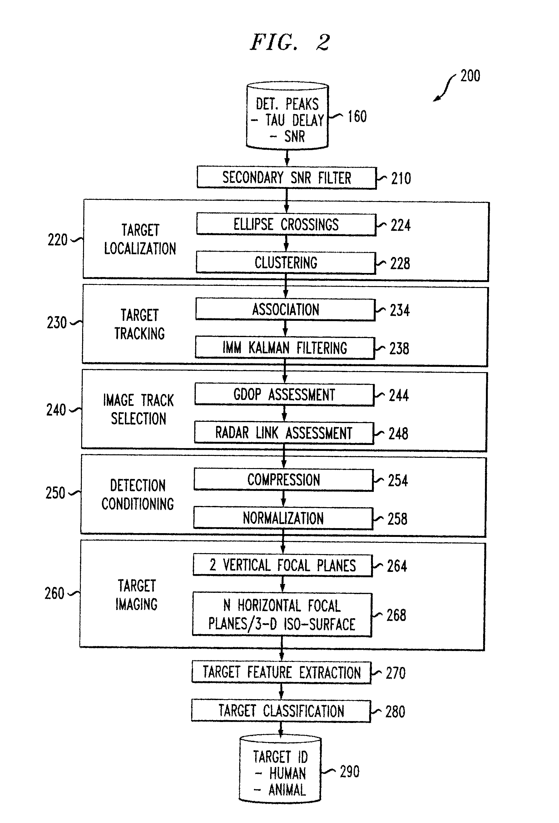
The present invention enables object image identification using a sparsely populated array of distributed radio nodes deployed and operated as a radar detection, tracking and identification application. The present invention recognizes that the employed radar sensors operate in the microwave RF spectrum, and thus are not masked by rain or fog. In addition, the employed radar sensors have sufficient range resolution to detect moving objects within dense foliage. Using a sparse array of radars mounted, for example, in fence posts enables the detection and tracking of intruders approaching the perimeter along with an automated recognition of nuisance alerts through formation and classification of an RF 3D image formed at selected points of the intruder's track.
One aspect of the invention includes the ability to form 3-D object images, from which estimates of extent and shape can be extracted for objects that are detected in the vicinity of the deployed radar array. Additionally, anothe...
PUM
 Abstract
Description
Claims
Application Information