Diffusion bonded lead connector

a technology of bonded lead and connector, which is applied in the direction of coupling device connection, non-electric welding apparatus, vacuum evaporation coating, etc., can solve the problems of increasing the cost of the resulting product and increasing the number of interconnections

Inactive Publication Date: 2011-11-03
MEDTRONIC INC
View PDF3 Cites 27 Cited by
  • Summary
  • Abstract
  • Description
  • Claims
  • Application Information

AI Technical Summary

Benefits of technology

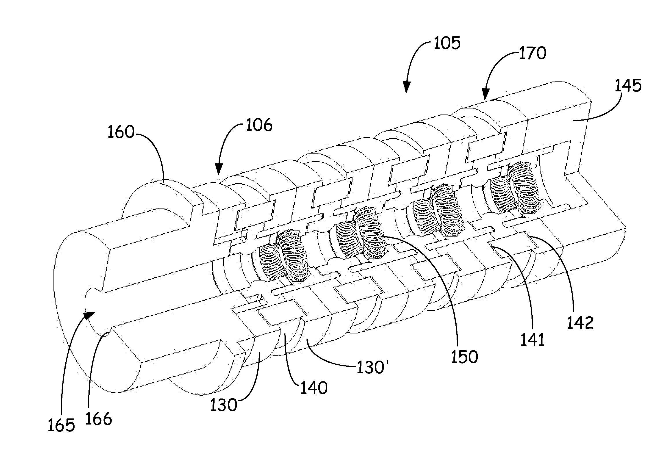
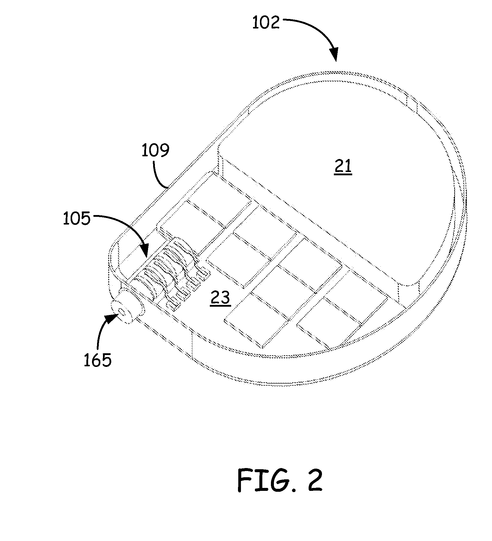
[0007]In another illustrative embodiment, an implantable medical device includes a hermetically sealed housing defining a sealed housing interior, a power source and electronics in electrical communication and disposed within the sealed housing interior, and a lead connector projecting into the sealed housing interior. The lead connector has an outer surface, and an inner surface defining a lead aperture. The lead connector includes one or more electrically conducting contact rings spaced apart by electrically insulating rings and joined together with a diffusion bond. The one or more electrically conducting contact rings are in electrical communication with the electronics. The diffusion bond provides a hermetic seal between the lead connector outer surface and the lead connector inner surface.

Problems solved by technology

While this arrangement has proven to be highly reliable, it involves a variety of expensive manufacturing processes and parts that necessarily increase the cost of the resulting product and increases the number of interconnects.

Method used


Image

  • Diffusion bonded lead connector
  • Diffusion bonded lead connector
  • Diffusion bonded lead connector

Examples


Embodiment Construction

[0019]In the following description, reference is made to the accompanying set of drawings that form a part hereof and in which are shown by way of illustration several specific embodiments. It is to be understood that other embodiments are contemplated and may be made without departing from the scope or spirit of the present disclosure. The following detailed description, therefore, is not to be taken in a limiting sense.

[0020]Unless otherwise indicated, all numbers expressing feature sizes, amounts, and physical properties used in the specification and claims are to be understood as being modified in all instances by the term “about.” Accordingly, unless indicated to the contrary, the numerical parameters set forth in the foregoing specification and attached claims are approximations that can vary depending upon the desired properties sought to be obtained by those skilled in the art utilizing the teachings disclosed herein.

[0021]As used in this specification and the appended claim...


PUM

PropertyMeasurementUnit
temperatureaaaaaaaaaa
temperaturesaaaaaaaaaa
thicknessaaaaaaaaaa

Abstract

A medical device lead connector includes electrically conducting contact rings spaced apart by an electrically insulating ring and in axial alignment. The electrically conducting contact ring and the insulating ring having an interface bond on an atomic level.

Description

[0001]The present application claims priority to U.S. Provisional Patent Application No. 61 / 329,260, filed Apr., 29, 2010, which application is hereby incorporated by reference as if re-written in its entiretyBACKGROUND[0002]Implantable active medical devices, such as cardiac rhythm management devices (pacemakers and defibrillators) and a variety of implantable muscle / nerve stimulators, for example, generally include a battery and battery-powered electronic pulse generator contained within a hermetically sealed housing or case and attached to a lead connector housing or block. The lead connector block is often affixed to the hermetically sealed housing with brackets, and / or a medical grade adhesive.[0003]The electronics within the hermetically sealed housing are conductively coupled to the lead connector block with an electrical feedthrough assembly. Electrical feedthroughs serve the purpose of providing a conductive path extending between the interior of a hermetically sealed conta...

Claims


Application Information

Patent Timeline
Patent Type & Authority Applications(United States)
IPC IPC(8): A61N1/36B32B38/00B32B37/06B32B37/14A61N1/04B32B37/02
CPCA61B2562/227A61N1/3752H01R13/187Y10T156/10H01R2107/00H01R2201/12H01R24/58B23K2101/38B23K2103/52B23K2103/54B23K2103/172B23K26/21A61N1/05B23K20/026C23C14/10C23C14/18C23C14/34H01R43/0221
Inventor JANZIG, DARREN A.THOM, ANDREW J.PAIDOSH, CHRIS J.TISCHENDORF, BRAD C.LINDNER, GERALD G.
Owner MEDTRONIC INC
Why Eureka
Try Eureka