Metal roof truss having generally s-shaped web members

a technology of metal roof trusses and web members, which is applied in the direction of girders, joists, trusses, etc., can solve the problems of increasing the cost of manufacture and production of metal trusses, c-shaped members are prone to flexural torsional buckling, and hot-rolled members are more expensive to manufacture than cold-rolled members. , to achieve the effect of improving the strength and performance of web members

Inactive Publication Date: 2011-11-17
DUNBAR DAVID C +2
View PDF2 Cites 2 Cited by
  • Summary
  • Abstract
  • Description
  • Claims
  • Application Information

AI Technical Summary

Benefits of technology

[0014]The web members preferably have a center of gravity and a center of shear which coincide. This improves the strength and performance of the web members. Further, the center of gravity and center of shear preferably fall within the cross-sectional area of the web member.

Problems solved by technology

A C-shaped member is prone to flexural torsional buckling for any given gauge or thickness of metal in comparison to a tubular or S-shaped web member.
The use of heavier gage metal or significant lateral bracing increases the cost of manufacture and production of the metal truss.
Hot-rolled members are more expensive to manufacture than cold-rolled members.
Similarly, the additional step of welding cold-rolled tubulars adds cost over cold-rolled tubulars without welding.

Method used


Image

  • Metal roof truss having generally s-shaped web members
  • Metal roof truss having generally s-shaped web members
  • Metal roof truss having generally s-shaped web members

Examples


Embodiment Construction

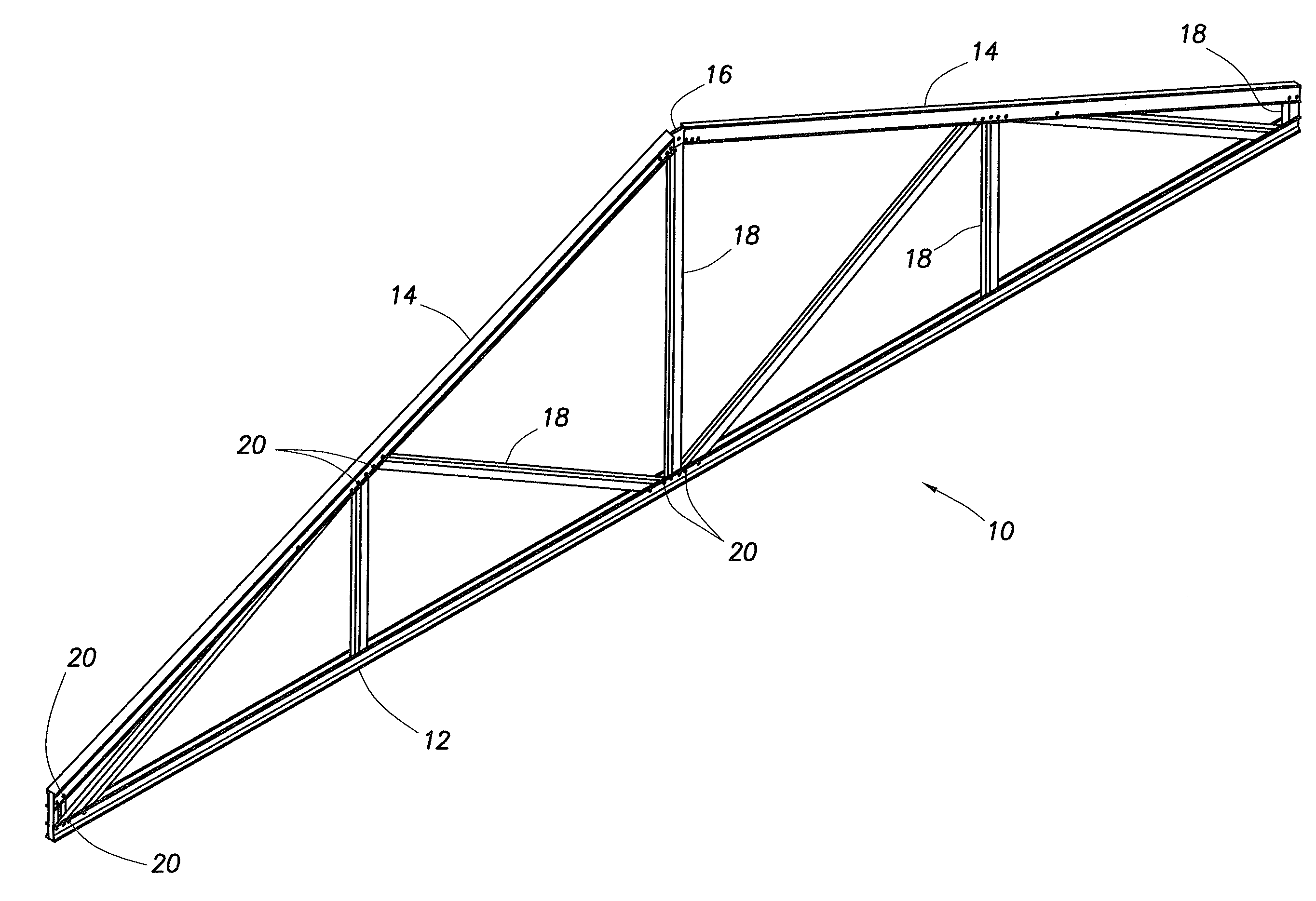
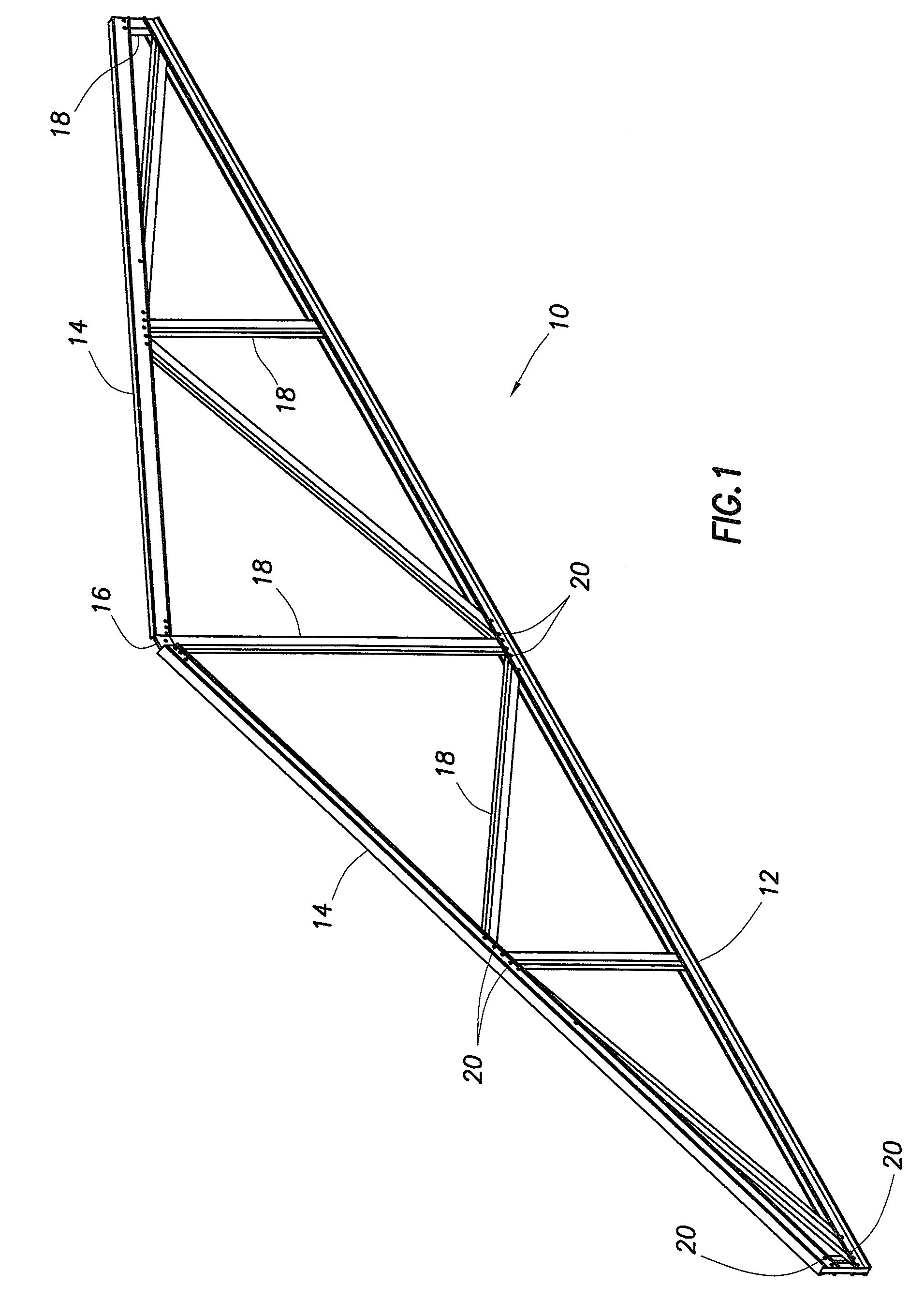
[0024]FIG. 1 is a perspective view of an exemplary metal truss 10. The truss 10 typically employs a bottom or lower chord 12 and two top or upper chords 14. The upper chords 14 are attached to one another at peak 16 by various means known in the art. The upper chords 14 and lower chord 12 are attached to one another, either directly using some means of attachment, or indirectly, through web members 18, as shown. A typical metal roof truss 10, as seen in FIG. 1, has two elongated, diverging upper chords 14 arranged opposed to one another. It is also possible to employ a single upper chord for flat roofs, floor trusses and the like, or three or more upper chords for more complicated or lengthy trusses. Typically, a single lower chord 12 is employed, however, it is also possible to employ two or more lower chords to provide extra length or allow for a truss having a vaulted design and the like.

[0025]Web members 18 and chords 12 and 14 are attached to one another. Multiple elongated met...


PUM


Abstract

The metal truss assembly disclosed herein is made from generally U-shaped metal chords and multiple generally S-shaped web members extending between the chords. A typical truss assembly has a pair of elongated, opposed, diverging metal upper chords and a lower chord, with the chords each forming generally U-shaped channels defining an interior chord space. A plurality of elongated metal web members extend between the upper and lower chords, with each of the web members extending into the interior space of an upper chord and the lower chord and attached to the chords. The web members, as taught herein, have a generally S-shaped cross-section. The shape of the web members is an advancement of prior art web members.

Description

CROSS-REFERENCE TO RELATED APPLICATIONS[0001]This application is a continuation of U.S. patent application Ser. No. 12 / 243,813 filed on Oct. 1, 2008, still pending.STATEMENT REGARDING FEDERALLY SPONSORED RESEARCH OR DEVELOPMENT[0002]Not applicableREFERENCE TO MICROFICHE APPENDIX[0003]Not applicableTECHNICAL FIELD[0004]The invention relates to a metal roof truss having an upper and lower chord and a plurality of web members extending between the chords, and more particularly, to such a truss wherein the web members are of a generally S-shaped cross-section.BACKGROUND OF THE INVENTION[0005]Metal roof trusses may take on various shapes, but the most commonly encountered shape is defined by two upper chords joined at adjacent ends and each connected to a lower chord to create a generally triangular truss. Extending between the upper and lower chords are a plurality of web members.[0006]The prior art teaches various cross-sectional shapes for the upper and lower chords, including general...

Claims


Application Information

Patent Timeline
Patent Type & Authority Applications(United States)
IPC IPC(8): E04C3/07
CPCE04C3/07E04C2003/0482E04C3/11
Inventor DUNBAR, DAVID C.BABICH, WILLIAM L.KELLING, GREG
Owner DUNBAR DAVID C
Why Eureka
Try Eureka