Multidirectionally reinforced shape woven preforms for composite structures

a multi-directional reinforced, composite material technology, applied in the direction of bridges, vehicular safety arrangments, synthetic resin layered products, etc., can solve the problems of parts that distort, dimple, ripple, and parts that cannot be of the same material or have comparable physical properties, and achieve the effect of improving strength

Active Publication Date: 2013-05-14
ALBANY ENGINEERED COMPOSITES
View PDF27 Cites 9 Cited by
  • Summary
  • Abstract
  • Description
  • Claims
  • Application Information

AI Technical Summary

Benefits of technology

[0019]The present invention relates to a method for combining fabrics formed using techniques, such as for example, bi-axial braiding, tri-axial braiding, polar weaving, warp steering weaving, contour weaving, and three-dimensional weaving, to produce a laminate that is multidirectionally reinforced and conforms easily to complex curvatures, such as for example, composite turbine fan cases, jet engine containment rings, aircraft fuselage frames, aircraft window frames, and flanged rings for attaching nacelles to aircraft engines. The present invention provides multidirectionally reinforced shaped woven preforms with improved strength for composite structures that are axisymmetric as well as non-axisymmetric in nature.
[0020]The combination of different forms of fabrics allows the preform to be produced without cutting and darting of the individual plies. Eliminating these cuts and darts improves the strength and performance of the resulting structure.

Problems solved by technology

Typically, however, they will not be of the same materials or have comparable physical, chemical, thermal or other properties, since a usual objective sought in using composites in the first place is to achieve a combination of characteristics in the finished product that is not attainable through the use of one constituent material alone.
However, this typically results in parts that distort when the preform is folded.
This causes dimples and ripples in areas where the as-woven fiber lengths are too short, and buckles in the areas where fiber lengths are too long.
These distortions cause undesirable surface anomalies and reduce the strength and stiffness of the component.
While this may be relieved by cutting and darting, such a procedure is undesirable, since it is labor intensive or otherwise may compromise the integrity of the preform.
This fabrication technique is not applicable to all geometrical shapes.
Furthermore, it is difficult to obtain a uniform coverage of material in a curved section using filament winding.
Although filament winding is a highly automated technology, filament winding a complex shape multi-layer laminate can require considerable time due to the low material dispensing rate.
However, the process can be slow and restricted to preimpregnated materials, and therefore expensive.
The production of a special weaving machine merely to produce a particular design structure is not only expensive, but also is confined to that particular design.
Additionally, these machines run at speeds relatively slower than the conventional weaving machine, because the insertion of the fill yarn follows a canted or curved path, which drastically reduces the loom speed.
Accordingly, mere use of conventional 2D or 3D woven preforms does not adequately provide the required strength in all directions.

Method used


Image

  • Multidirectionally reinforced shape woven preforms for composite structures
  • Multidirectionally reinforced shape woven preforms for composite structures
  • Multidirectionally reinforced shape woven preforms for composite structures

Examples


Embodiment Construction

[0049]The instant invention will now be described more fully hereinafter with reference to the accompanying drawings, in which preferred embodiments of the invention are shown. This invention may, however, be embodied in many different forms and should not be construed as limited to the illustrated embodiments set forth herein. Rather, these illustrated embodiments are provided so that this disclosure will be thorough and complete, and will fully convey the scope of the invention to those skilled in the art.

[0050]In the following description, like reference characters designate like or corresponding parts throughout the figures. Additionally, in the following description, it is understood that such terms as “upper,”“lower,”“top” and “bottom” and the like are words of convenience and are not to be construed as limiting terms.

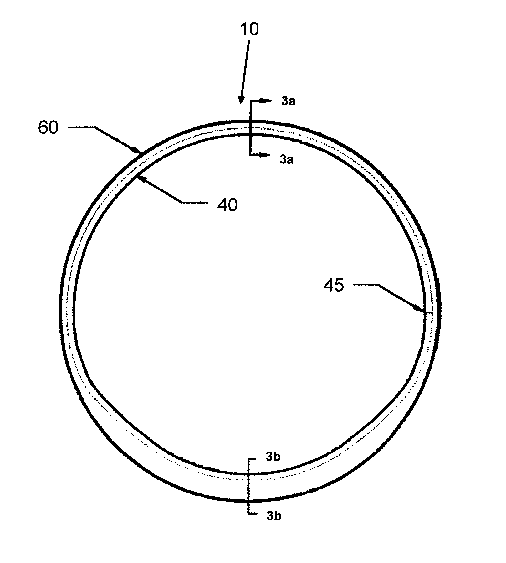
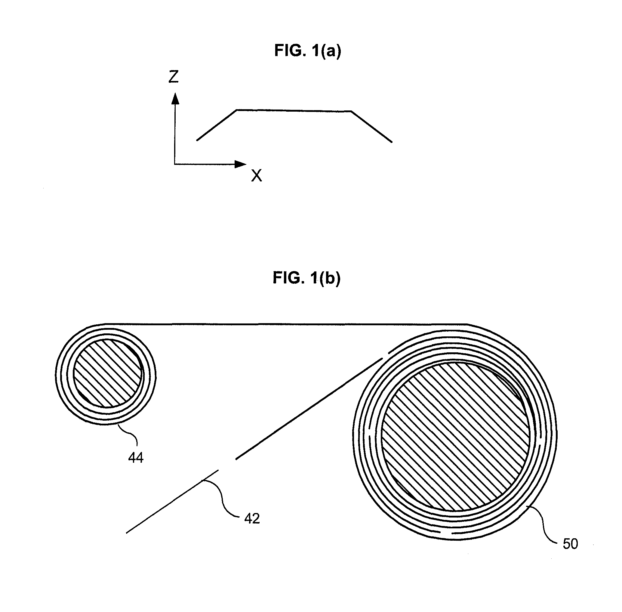
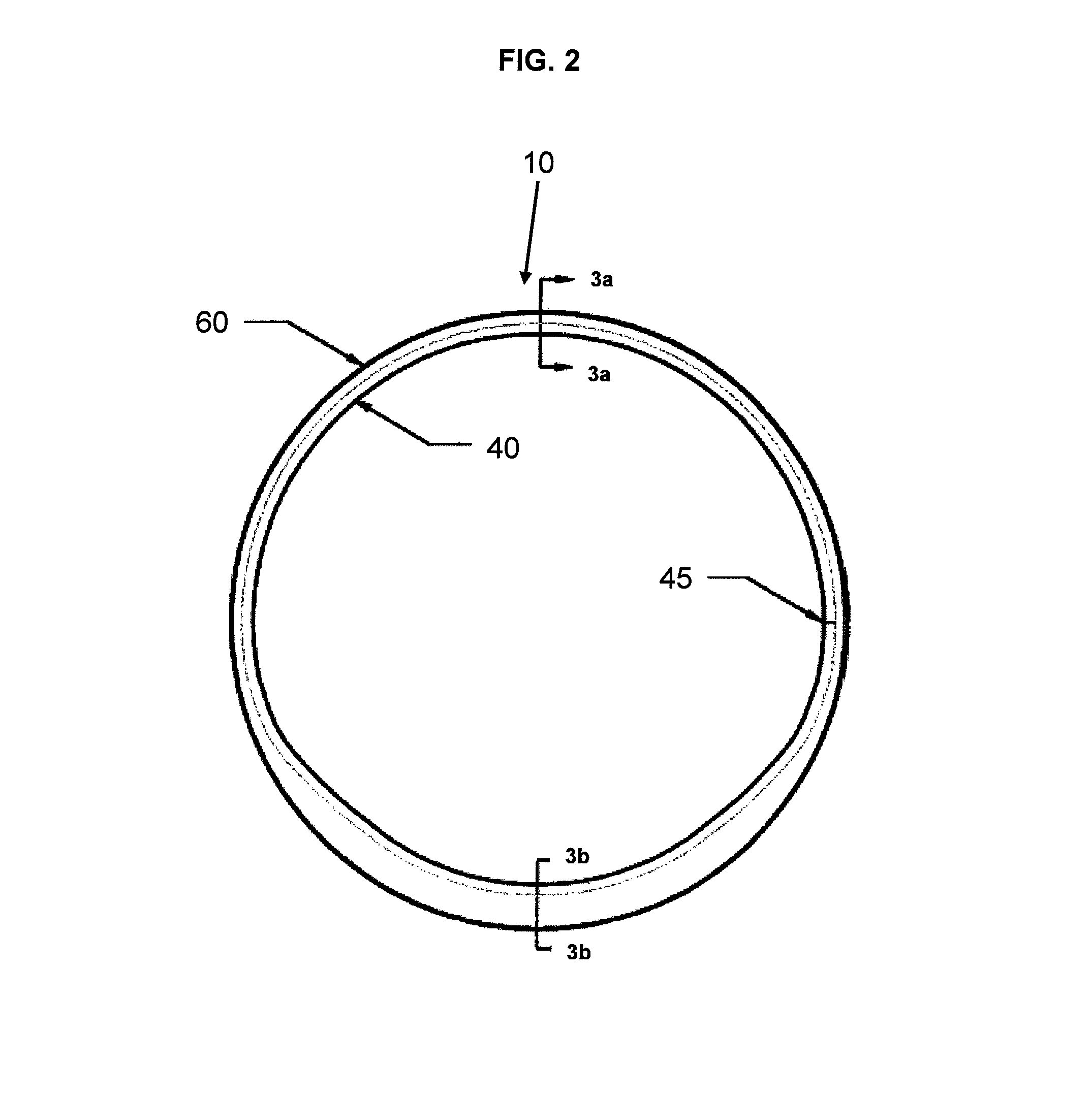
[0051]Turning now to the figures, the invention according to one embodiment is a method of fabricating a multidirectionally reinforced fiber preform for use in h...


PUM

PropertyMeasurementUnit
oblique anglesaaaaaaaaaa
structureaaaaaaaaaa
warp lengthsaaaaaaaaaa

Abstract

The present invention relates to multidirectionally reinforced fiber preforms that conform easily to complex curvatures, such as, composite turbine fan cases, jet engine containment rings, aircraft fuselage frames, aircraft window frames, and flanged rings for attaching nacelles to aircraft engines. The present invention provides multidirectionally reinforced shape woven preforms with improved strength for composite structures that are axisymmetric as well as non-axisymmetric in nature. The invention is a preform used to reinforce a composite structure which includes a contour woven fabric portion, bi-axially braided, tri-axially braided or bias fabric portion, and / or a polar woven fabric portion, and a method of making thereof. The preform may optionally include a three-dimensionally woven portion. The combination of different forms of fabrics allows the preform to be produced without cutting and darting of the individual plies. Eliminating these cuts and darts improves the strength and performance of the resulting structure.

Description

BACKGROUND OF THE INVENTION[0001]1. Field of the Invention[0002]The present invention relates to woven preforms for reinforced composite materials and, in particular, to multidirectionally reinforced shape woven preforms for composite structures.[0003]2. Incorporation by Reference[0004]All patents, patent applications, documents, references, manufacturer's instructions, descriptions, product specifications, and product sheets for any products mentioned herein are incorporated herein by reference, and may be employed in the practice of the invention.[0005]3. Description of the Prior Art[0006]The use of reinforced composite materials to produce structural components is now widespread, particularly in applications where their desirable characteristics are sought of being light in weight, strong, tough, thermally resistant, self-supporting and adaptable to being formed and shaped. Such components are used, for example, in aeronautical, aerospace, satellite, recreational (as in racing bo...

Claims


Application Information

Patent Timeline
Patent Type & Authority Patents(United States)
IPC IPC(8): B32B23/00B32B1/00D03D11/00B32B1/08B32B27/02B32B27/30B32B27/36B32B5/26B32B25/02B32B27/38B32B27/04D06P7/00D04C1/00D03D9/00D03D13/00
CPCB32B5/024B32B5/26B64C1/1492D03D25/005B29B11/16D03D3/08B32B5/12Y10T428/1314B32B2250/20B32B2250/42B32B2605/18D10B2505/02Y10T428/2481Y10T428/1393Y10T428/1362Y10T428/1379B32B1/08B32B3/04B32B3/28B32B2260/021B32B2260/046B32B2262/0253B32B2262/0261B32B2262/0269B32B2262/0276B32B2262/04B32B2262/062B32B2262/101B32B2262/105B32B2262/106B32B2307/306B32B2307/50B32B2307/558B32B2307/718B29L2031/005B32B7/05Y10T428/249922Y10T442/133Y10T442/3594Y10T442/3585Y10T442/3561Y10T442/3528Y10T442/3203Y10T442/3211Y10T442/3187Y10T442/3195D03D1/00D03D11/00D03D15/00
Inventor ROSE, DONALDGOERING, JONATHANBIDDLE, STEVE
Owner ALBANY ENGINEERED COMPOSITES
Why Eureka
Try Eureka