Vehicle latch device

a technology for latching devices and vehicles, which is applied in the direction of carpet fasteners, locks, mechanical devices, etc., can solve the problems of cleaning water, inability to arrange the latch device on the door, and the size of the locking device is increased

Inactive Publication Date: 2011-11-17
MITSUI KINZOKU ACT
View PDF17 Cites 17 Cited by
  • Summary
  • Abstract
  • Description
  • Claims
  • Application Information

AI Technical Summary

Problems solved by technology

Therefore, there is a probability that cleaning water accompanying vehicle cleaning or rainwater leaks into the locking device from a gap between a door handle and a door and enters into an interior of the locking device via an operation cable.
However, if the portion is simply covered with a case, there is a problem that the locking device is made larger and cannot be arranged on the door.

Method used


Image

  • Vehicle latch device
  • Vehicle latch device
  • Vehicle latch device

Examples


first embodiment

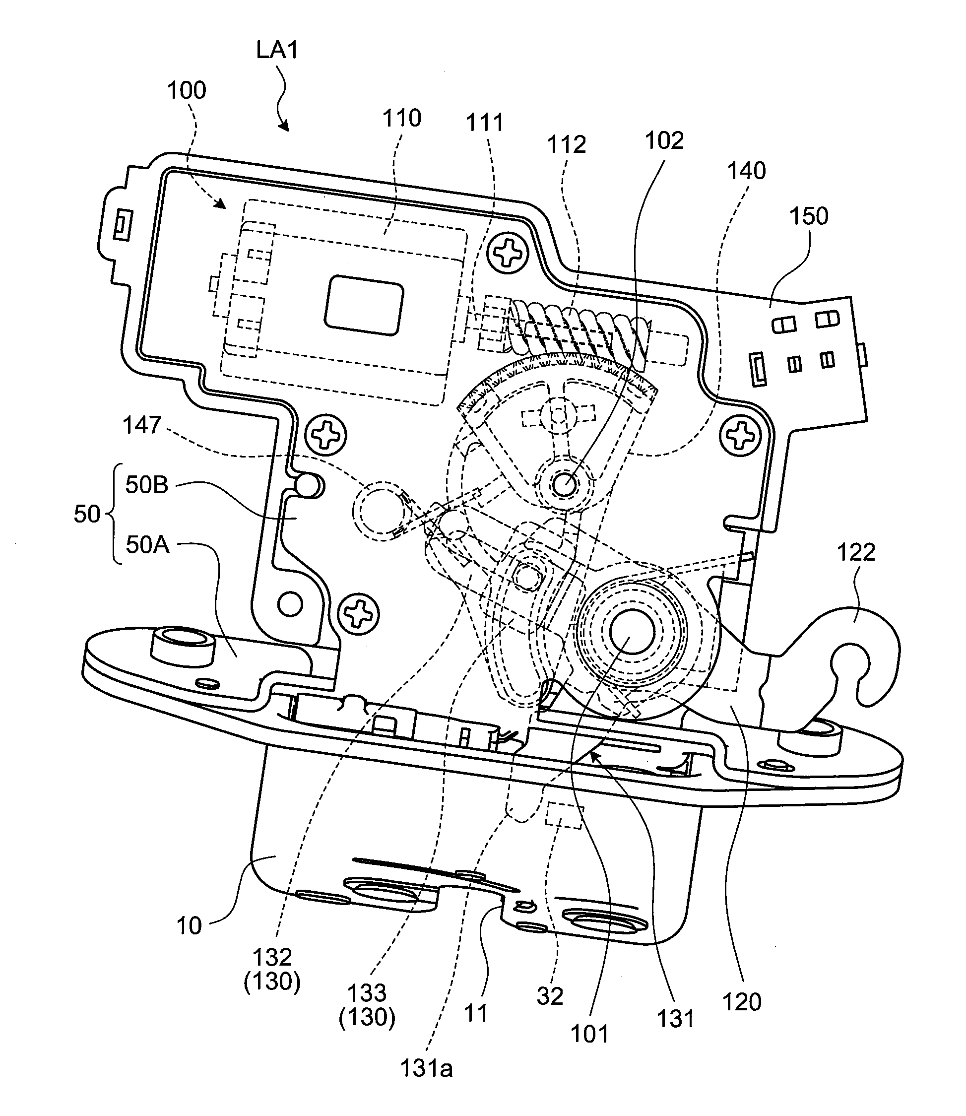
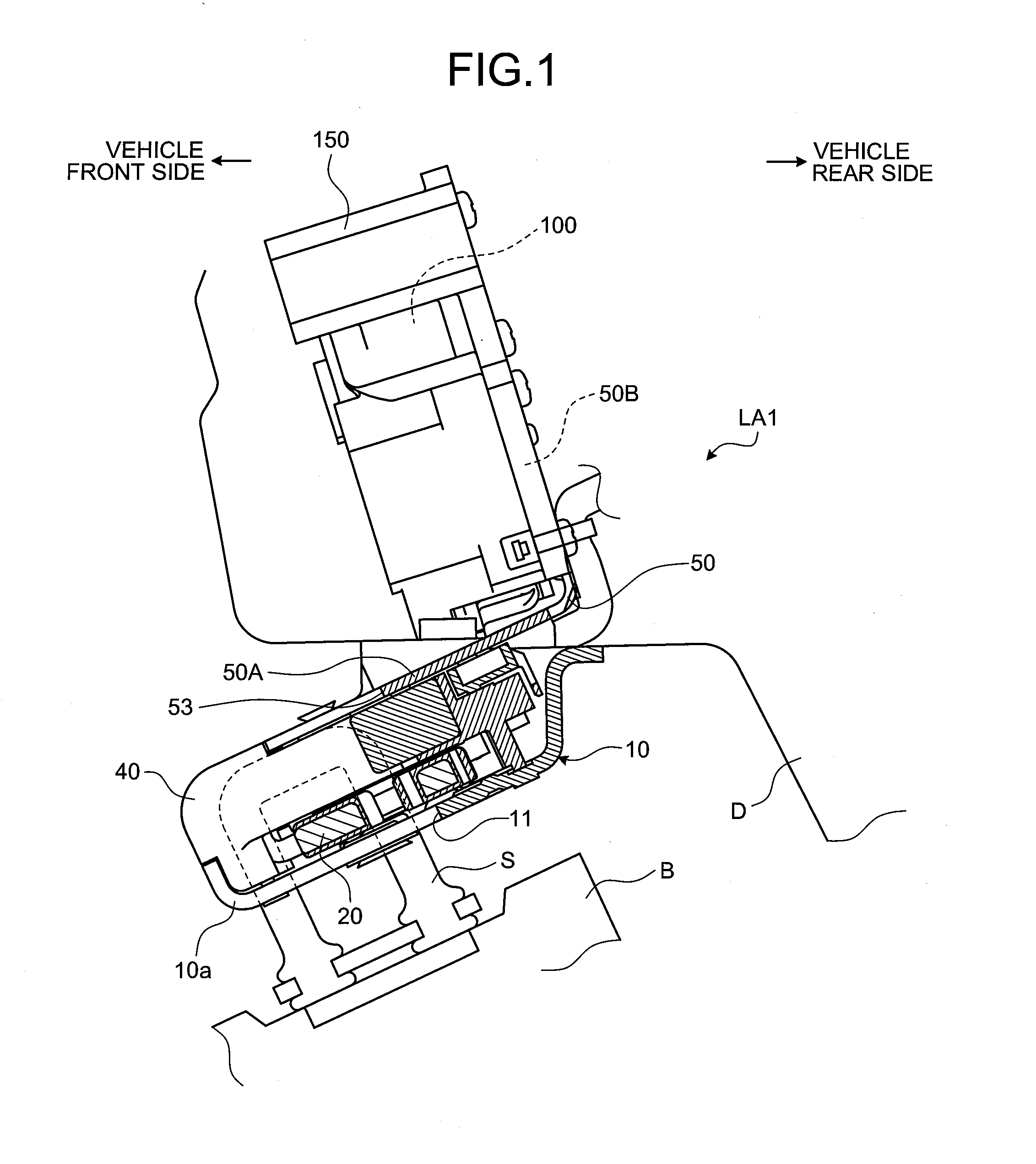
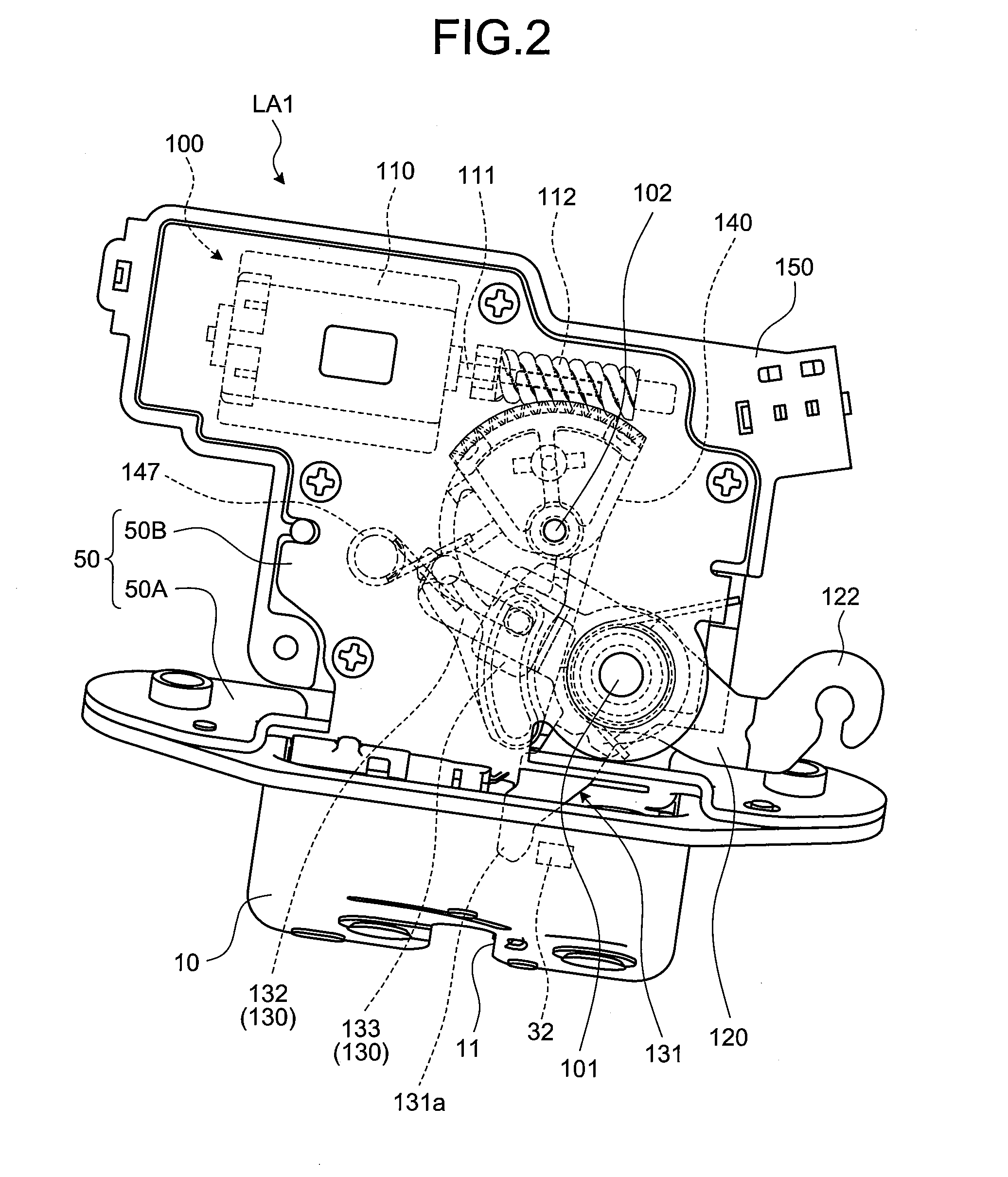
[0041]FIGS. 1 to 3 depict a vehicle latch device according to the present invention. A vehicle latch device LA1 exemplarily described here is designed to keep a back door D referred to as “tail gate” closed to a vehicle main body B by engaging the vehicle latch device LA1 with a striker S provided on the vehicle main body B of a four-wheeled vehicle as shown in FIG. 4. The vehicle latch device LA1 is an electric locking / unlocking door latch device a state of which is switched between a locking state and an unlocking state by driving an electric actuator. The back door D, which is supported by an upper edge of a rear end of the vehicle main body B, opens or closes an opening on the rear end of the vehicle main body B by being axially rotated about a center of a shaft along a transverse direction.

[0042]FIGS. 5A to 5C are plan views of the vehicle latch device LA1 for schematically depicting an engagement state where the striker S provided on the vehicle main body B is engaged with a l...

second embodiment

[0081]FIG. 20 is a front view of the vehicle latch device LA2 according to the FIG. 21 is a rear view of the vehicle latch device LA2 shown in FIG. 20. FIG. 22 is a front view of the vehicle latch device LA2 for depicting that a unit cover is detached from an actuator unit when the vehicle latch device LA2 shown in FIG. 20 is at a fully latched position. FIG. 23 is a perspective view of the vehicle latch device LA2 for depicting an interior of the vehicle latch device LA2 when the vehicle latch device LA2 shown in FIG. 20 is at the fully latched position and the unit cover is detached from the actuator unit. FIG. 24 is a front view of a cable lever applied to the actuator unit of the vehicle latch device LA2 shown in FIG. 20.

[0082]As shown in FIGS. 20 to 22, the vehicle latch device LA2 includes the cover plate 10, the main-unit body 40, and the back plate 50.

[0083]The actuator unit 100 held by the back plate 50 is a driving unit that disengages the latch 20 from the ratchet 30. As...


PUM


Abstract

A vehicle latch device including: a releasing unit that rotates about a support shaft provided on a holding member of an electric actuator and includes a cam pin and an output unit that disengages a latch from a ratchet by rotation of the releasing unit about the support shaft, where a driving force of the electric actuator being input to the cam pin; and a gear member that rotates about the support shaft, connects the electric actuator to the releasing unit, and inputs a driving force of the electric actuator into the input unit. The cam pin is arranged to be superimposed on a plane of rotation of the gear member, and the vehicle latch device further includes a cover member that is attached to the holding member and covers at least the support shaft, the input unit, the electric actuator, and the gear member.

Description

BACKGROUND OF THE INVENTION[0001]1. Field of the Invention[0002]The present invention relates to a vehicle latch device including an actuator unit.[0003]2. Description of the Related Art[0004]Conventionally, as a vehicle latch device, there has been known a locking device arranged on a vehicle door and capable of not only disengaging a latch from a striker by manipulating a door handle connected to the locking device via an operation cable to open the door, but also disengaging the latch from the striker by operating an electric actuator such as a motor to open the door (see, for example, Japanese Patent No. 3985935).[0005]The conventional locking device disclosed in Japanese Patent No. 3985935 is arranged on a vehicle door. Therefore, there is a probability that cleaning water accompanying vehicle cleaning or rainwater leaks into the locking device from a gap between a door handle and a door and enters into an interior of the locking device via an operation cable. Therefore, it is ...

Claims


Application Information

Patent Timeline
Patent Type & Authority Applications(United States)
IPC IPC(8): E05B15/02E05B77/34E05B81/34E05B81/44E05B83/16E05B83/18
CPCE05B81/06E05B81/14E05B81/25E05B81/34E05B81/36Y10S292/42E05B81/50E05B85/02E05B85/26E05B81/00E05B81/44Y10T292/1082Y10T292/308Y10T292/699
Inventor WATANABE, HIROFUMINAKATSUKA, FUYUKI
Owner MITSUI KINZOKU ACT
Why Eureka
Try Eureka