Connector assemblies including movable connectors

Inactive Publication Date: 2011-11-17
TE CONNECTIVITY CORP
View PDF6 Cites 9 Cited by
  • Summary
  • Abstract
  • Description
  • Claims
  • Application Information

AI Technical Summary

Benefits of technology

[0005]In one embodiment, a connector assembly is provided that is configured to facilitate aligning and engaging first and second mating terminals to establish a communication pathway. The connector assembly includes a first connector that is configured to be movably mounted to a support structure and has at least one first mating terminal. The first connector is movable with respect to the support structure in an axial direction along an alignment axis. The connector assembly also includes a second connector that is configured to be slidably mounted to a support panel and has at least one second mating terminal. The second connector is slidable along the support panel in a radial direction with respect to the alignment axis. The second connector shifts in the radial direction to align the first and second mating terminals when the first and second connectors engage each other in a misaligned manner. The first connector moves between a projected position and a retracted position along the alignment axis to facilitate establishing a communication pathway between the first and second mating terminals.

Problems solved by technology

In some operating environments, an individual attempting to mate the two connectors may be unable to view the two connectors as the connectors engage each other.
In such “blind mating” situations, the technician risks damaging the two connectors if the two connectors engage each other in a misaligned manner.
However, such connector assemblies may have limited capabilities.
Also, the floatable connectors may be limited to either side-to-side movement or vertical (up-down) movement.
Furthermore, if the force applied to the mating connector is excessive, the floatable connector may be unable to adjust and at least one of the connectors may be damaged.

Method used


Image

  • Connector assemblies including movable connectors
  • Connector assemblies including movable connectors
  • Connector assemblies including movable connectors

Examples


Embodiment Construction

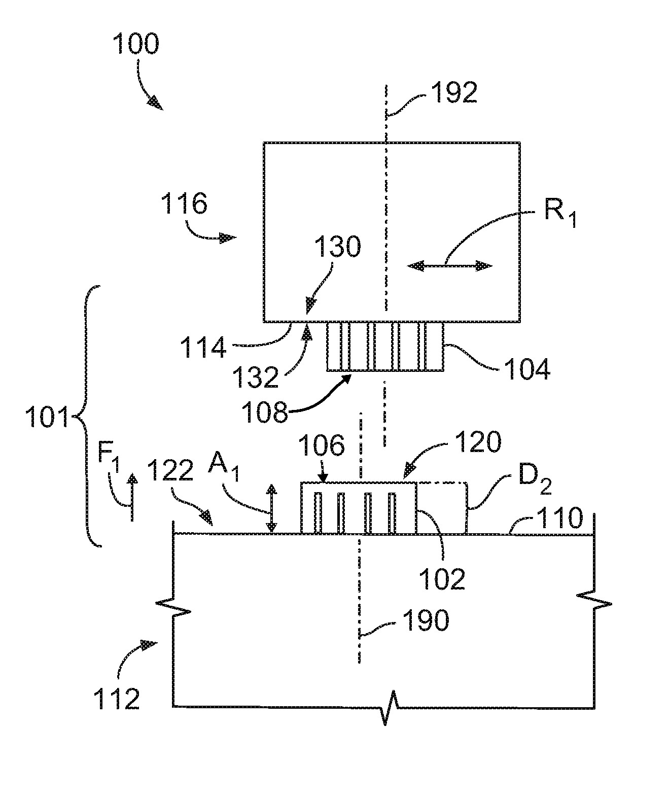
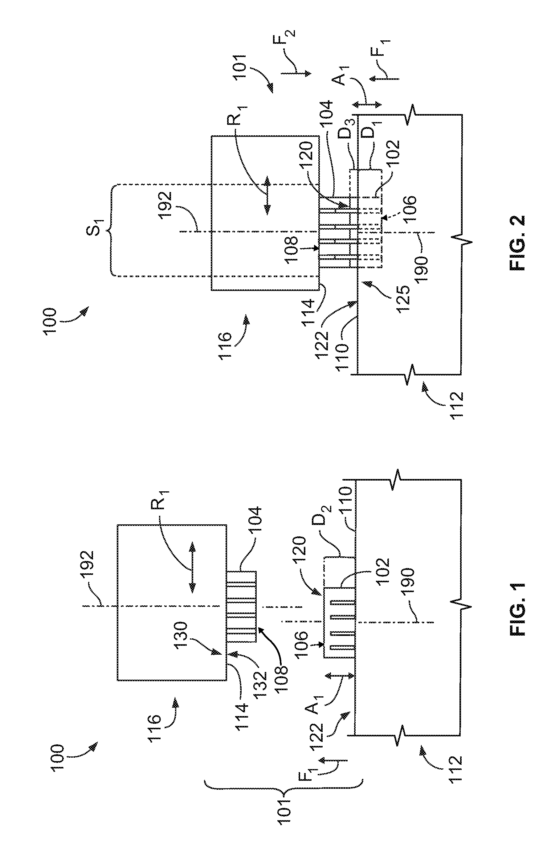
[0022]FIGS. 1 and 2 are schematic illustrations of a connector system 100 that includes a connector assembly 101 formed in accordance with one embodiment. The connector assembly 101 includes first and second connectors 102 and 104. FIG. 1 shows the first and second connectors 102 and 104 in a disengaged state or positional relationship, and FIG. 2 shows the first and second connectors in a communicatively engaged state or positional relationship. The first and second connectors 102 and 104 include first and second mating terminals 106 and 108, respectively, that are configured to communicatively couple to each other to establish at least one of an electrical and an optical connection. The mating terminals 106 and 108 may be housed or enclosed within the first and second connectors 102 and 104 or the mating terminals 106 and 108 may project therefrom into surrounding space. The mating terminals may include socket contacts and mating pins in which the socket contacts are configured to...


PUM


Abstract

A connector assembly including a first connector configured to be movably mounted to a support structure and having a first mating terminal. The first connector is movable with respect to the support structure in an axial direction along an alignment axis. The connector assembly also includes a second connector that is configured to be movably mounted to a support panel and has a second mating terminal. The second connector is movable with respect to the support panel in a radial direction relative to an alignment axis. The second connector shifts in the radial, direction to align the first and second mating terminals when the first and second connectors engage each other in a misaligned manner. The first connector moves between a projected position and a retracted position along the alignment axis to facilitate establishing a communication pathway between the first and second mating terminals.

Description

BACKGROUND OF THE INVENTION[0001]The subject matter herein relates generally to connector assemblies, and more particularly, to connector assemblies configured to self-align connectors during a mating operation.[0002]Connector assemblies may be used to establish communication pathways between electrical contacts or between optical fiber terminals. Exemplary connector assemblies include two separate connectors that may be sized, shaped, or otherwise configured to mate with one another to establish the communication pathway(s). In some operating environments, an individual attempting to mate the two connectors may be unable to view the two connectors as the connectors engage each other. In such “blind mating” situations, the technician risks damaging the two connectors if the two connectors engage each other in a misaligned manner.[0003]Various connector assemblies have been proposed for tolerating misalignments between the connectors during a mating operation. Such connector assembli...

Claims


Application Information

Patent Timeline
IPC IPC(8): H01R13/64
CPCH01R13/743H01R13/6315
Inventor TANIS, WILLIAM E.WILLIAMS, BRIAN J.MCDOWELL, PAUL WALTER
Owner TE CONNECTIVITY CORP
Why Eureka
Try Eureka