Distraction Screw

Active Publication Date: 2011-11-17
GLOBUS MEDICAL INC
View PDF7 Cites 54 Cited by
  • Summary
  • Abstract
  • Description
  • Claims
  • Application Information

AI Technical Summary

Benefits of technology

The present invention provides a distraction screw which includes a proximal portion secured to a first vertebra, a distal portion secured to a second vertebra and an intermediate portion. The intermediate portion is coupled to the

Problems solved by technology

Bones and bony structures are susceptible to a variety of weakness

Method used


Image

  • Distraction Screw
  • Distraction Screw
  • Distraction Screw

Examples


Embodiment Construction

While it is apparent that the invention disclosed herein is well calculated to fulfill the objects stated above, it will be appreciated that numerous modifications and embodiments may be devised by those skilled in the art.

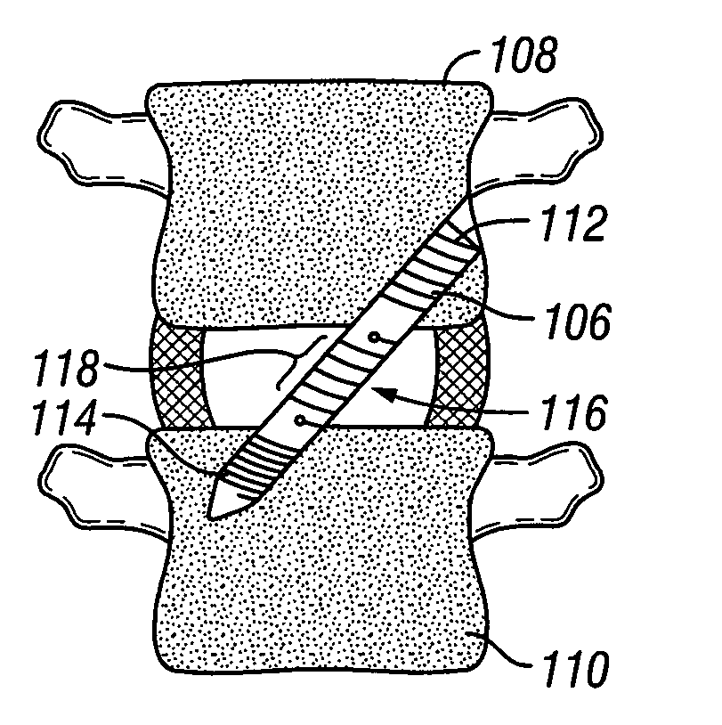
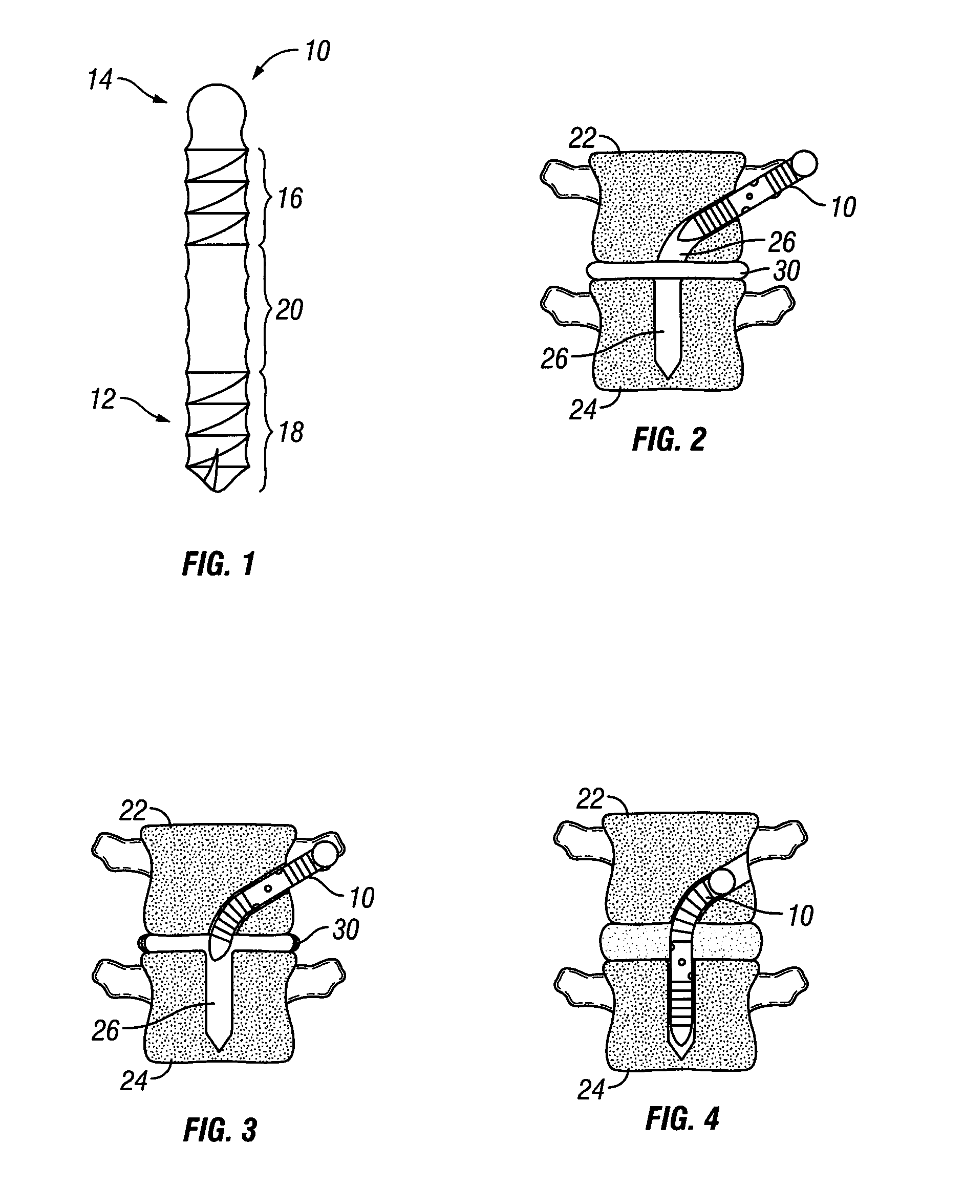
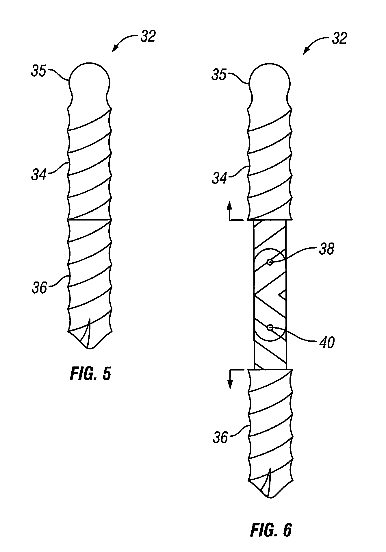
FIGS. 1-4 illustrate an axially distracting screw and a method for laterally positioning the screw within the spine. FIG. 1 shows a distracting screw 10 having a shank portion 12 and a head portion 14. The shank portion 14 includes a first semi-rigid portion 16 and a second semi-rigid portion 18. The shank portion 14 is also configured with a rigid portion 20 positioned between the first and second semi-rigid portions 16 and 18. The first semi-rigid portion 16 and the second semi-rigid portion 18 are provided with threads that enable bone purchase and allow for the screw to advance through the bone in a curved trajectory. When the distraction screw 10 is threaded into its final position, the rigid portion 20 is positioned to be between the two endplates of the adj...


PUM


Abstract

A distraction screw includes a proximal portion secured to a first vertebra, a distal portion secured to a second vertebra and an intermediate portion. The intermediate portion is coupled to the proximal and distal portions and is positioned in an intervertebral space. The intermediate portion is configured and adapted to enable distraction of the first vertebra relative to the second vertebra.

Description

FIELD OF THE INVENTIONThe present disclosure generally relates to a fixation device for positioning and immobilizing at least two adjacent vertebra.BACKGROUND OF THE INVENTIONBones and bony structures are susceptible to a variety of weaknesses that can affect their ability to provide support and structure. Weaknesses in bony structures may have many causes, including degenerative diseases, tumors, fractures, and dislocations. Advances in medicine and engineering have provided doctors with a plurality of devices and techniques for alleviating or curing these weaknesses. Typically, weaknesses in the spine are corrected by using devises that fuse one or more vertebrae together. There is a need for variations of a new screw that can be used to distract vertebrae and restore as well as maintain disc height while keeping the lumber vertebrae in its natural alignment through a combination of rigid / semi-rigid or pivoting screw segments.SUMMARY OF THE INVENTIONThe present invention provides ...

Claims


Application Information

Patent Timeline
IPC IPC(8): A61B17/70
CPCA61B17/70A61B17/8685A61B17/863A61B17/88A61B17/844A61B17/84A61B17/56A61B17/86A61B2017/564A61B17/864
Inventor SUH, SEANZENTKO, MICHALIOTT, ANDREWFAULHABER, KURTPAUL, DAVID C.
Owner GLOBUS MEDICAL INC
Why Eureka
Try Eureka