Developing device and image forming apparatus including the same

a technology of image forming apparatus and development device, which is applied in the direction of electrographic process apparatus, instruments, optics, etc., can solve the problems of reducing the density of an image printed on a recording medium, and affecting the quality of the imag

Active Publication Date: 2011-11-24
SHARP KK
View PDF4 Cites 14 Cited by
  • Summary
  • Abstract
  • Description
  • Claims
  • Application Information

AI Technical Summary

Benefits of technology

[0033]Accordingly, the image forming apparatus provided with the developing device according to the present invention can allow the developer to smoothly circulate through the first developer conveying passage and the second developer conveying passage, whereby the developer in a sufficient amount is supplied to the photoconductor drum through the developing roller. Consequently, an image can be printed on a recording medium with a satisfactory image density.

Problems solved by technology

However, in the developing devices described in Prior Art 1 and Prior Art 2, the developer receives a violent pressure in an advancing direction, and receives a shear force in such a pressurized state, at the position, facing the communicating path, at the end of the downstream side of the auger screw.
Due to a generation of heat and the shear force caused by a stress, a flow improver, which is an external additive of a toner, is unfavorably be embedded into a particle of a resin constituting the toner, which might cause an extreme deterioration in a flow property of the developer, and hence, a phenomenon in which the conveyance of the developer becomes difficult might be produced.
Consequently, it becomes difficult to supply the developer in a sufficient amount to a photoconductor drum through a developing roller, which might cause a problem that a density of an image printed on a recording medium is reduced.

Method used


Image

  • Developing device and image forming apparatus including the same
  • Developing device and image forming apparatus including the same
  • Developing device and image forming apparatus including the same

Examples


first embodiment

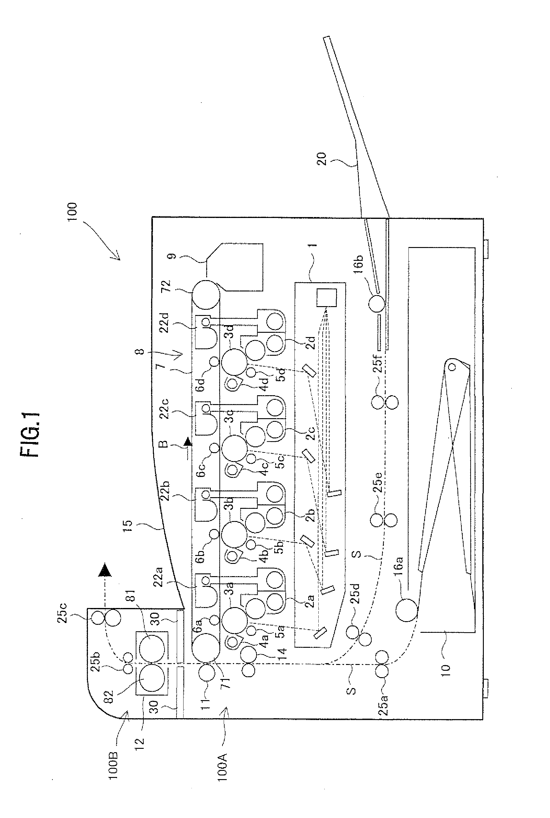
[0082]FIG. 1 is an explanatory illustration showing an overall structure of an image forming apparatus including a developing device according to a first embodiment of the present invention.

[0083]An image forming apparatus 100 is a printer capable of forming a multi-color or single-color image on a sheet-like recording medium (recording sheet) based on image data externally received, the image forming apparatus 100 including: a developing device housing 100A in which a plurality of developing devices 2a to 2d are each accommodated in a casing; a fusing device housing 100B in which a fusing device 12 is accommodated above the developing device housing 100A inside the casing; and a partition wall 30 disposed between the developing device housing 100A and the fusing device housing 100B for insulating the heat generated by the fusing device 12.

[0084]A top face of the developing device housing 100A positioned beside the fusing device housing 100B serves as a sheet exit tray 15.

[0085]In t...

second embodiment

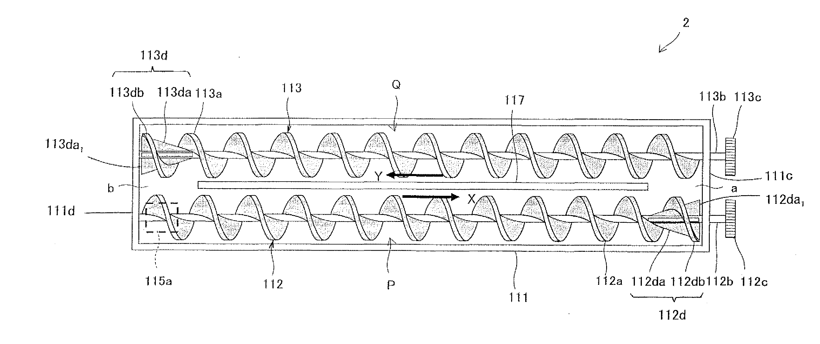
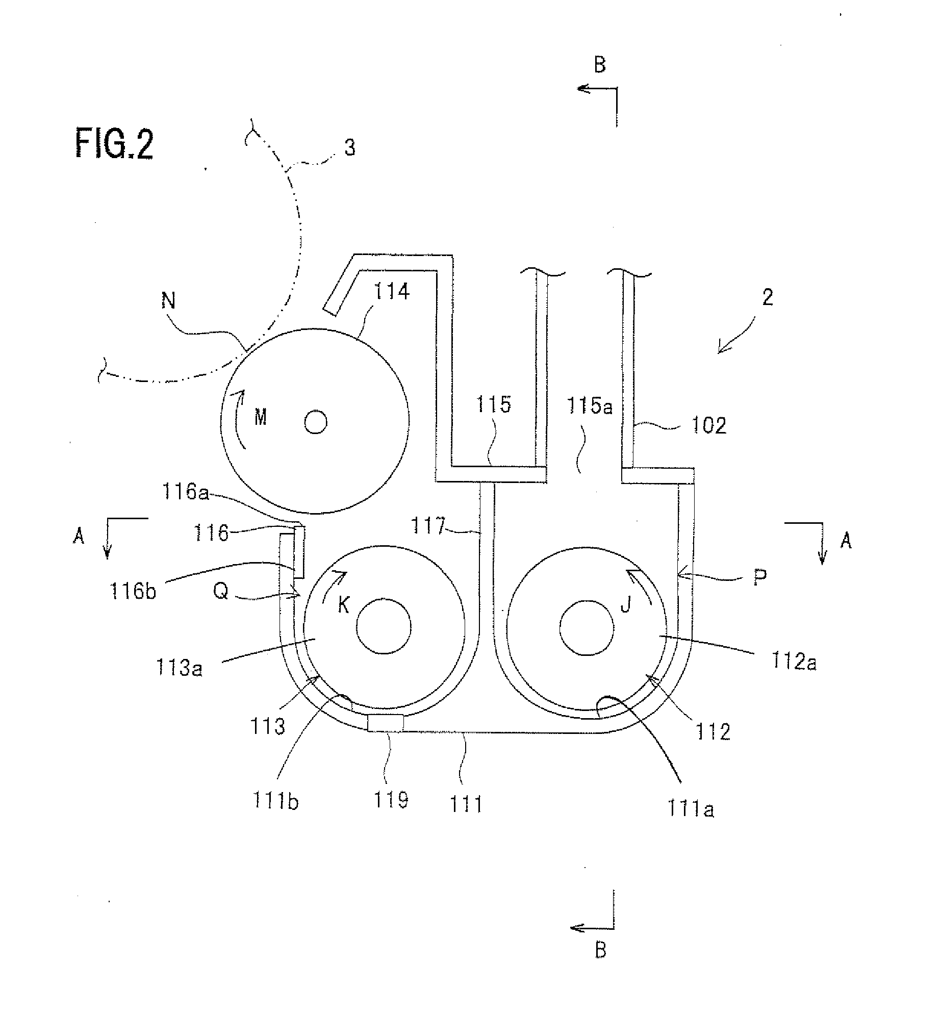
[0185]FIG. 11 is a horizontal cross-sectional view showing a developing device according to a second embodiment of the present invention. FIG. 12 is a side cross-sectional view of the developing device according to the second embodiment. FIG. 13 is an exploded view of an end blade of a first developer conveying helical member shown in FIG. 12. FIG. 14 is a view of a circumferential-direction agitating blade portion of the end blade taken along a line E-E in FIG. 13. FIG. 15 is a perspective view of the circumferential-direction agitating blade portion shown in FIG. 14. The components in FIGS. 11 and 12 same as those in FIGS. 3 and 4 are identified by the same numerals.

[0186]A developing device 202 according to the second embodiment is the same as the developing device according to the first embodiment, except for end blades 212d and 213d of a first developer conveying helical member 212 and a second developer conveying helical member 213. Therefore, a description will be given herei...


PUM


Abstract

A developing device to be installed in an electrophotographic image forming apparatus including a photoconductor drum that is to have an electrostatic latent image formed on a surface thereof, the developing device comprising: a developer vessell; a developing roller that is disposed in the developer vessel; first and second developer conveying passages; and first and second developer conveying helical members circulatory conveys the developer in the first and second developer conveying passages, wherein
    • at least one of the first and second developer conveying helical members includes an end blade at one end at a downstream side in a conveying direction, wherein
    • the end blade includes a circumferential-direction agitating blade portion whose radial projecting size gradually increases toward the downstream side in the conveying direction; and a helical blade portion integrally wound around an outer periphery of the circumferential-direction agitating blade portion.

Description

CROSS-REFERENCE TO RELATED APPLICATION[0001]This application is related to Japanese patent application No. 2010-116489 filed on May 20, 2010 whose priority is claimed under 35 USC §119, the disclosure of which is incorporated by reference in its entirety.BACKGROUND OF THE INVENTION[0002]1. Field of the Invention[0003]The present invention relates to a developing device using a dual-component developer and an image forming apparatus including the same.[0004]2. Description of the Background Art[0005]In recent years, for electrophotographic image forming apparatuses supporting full-color and high-quality images, a dual-component developer (hereinafter simply referred to as the “developer”) which exhibits an excellent charge performance stability as to a toner is in widespread use.[0006]The developer is made up of the toner and a carrier, which are agitated in a developing device and frictionally rubbed with each other to produce an appropriately electrified toner.[0007]In the developin...

Claims


Application Information

Patent Timeline
Patent Type & Authority Applications(United States)
IPC IPC(8): G03G15/08
CPCG03G2215/0827G03G15/0877G03G15/0893G03G15/0879
Inventor HAYASHI, SHIGEKINAGAI, TAKAFUMI
Owner SHARP KK
Why Eureka
Try Eureka