Toner for developing electrostatic latent image
- Summary
- Abstract
- Description
- Claims
- Application Information
AI Technical Summary
Benefits of technology
Problems solved by technology
Method used
Image
Examples
first embodiment
[0082]Toner for developing an electrostatic latent image according to the present embodiment is a dry developer containing toner particles having a core-shell structure and a resin-coated carrier.
[0083]
[0084]A method of forming resin particles in advance with such a polymerization method as an emulsion polymerization method or a suspension polymerization method and forming particles by aggregating and fusing these resin particles is preferred as a method of manufacturing toner particles having a core-shell structure.
[0085]In the emulsion polymerization method, toner particles having a core-shell structure are fabricated generally through the following procedures. Namely,
[0086](1) a step of fabrication of a dispersion solution of resin particles for cores,
[0087](2) a step of fabrication of a dispersion solution of pigment particles,
[0088](3) a step of aggregation and fusion of the resin particles for cores (step of fabricating core particles),
[0089](4) a first aging step,
[0090](5) a ...
example 1
[0171]In Example 1, the dry developer in the first embodiment, that is, the dry developer composed of the toner particles having the core-shell structure and the resin-coated carrier, was fabricated.
Preparation of Additive Particles 1
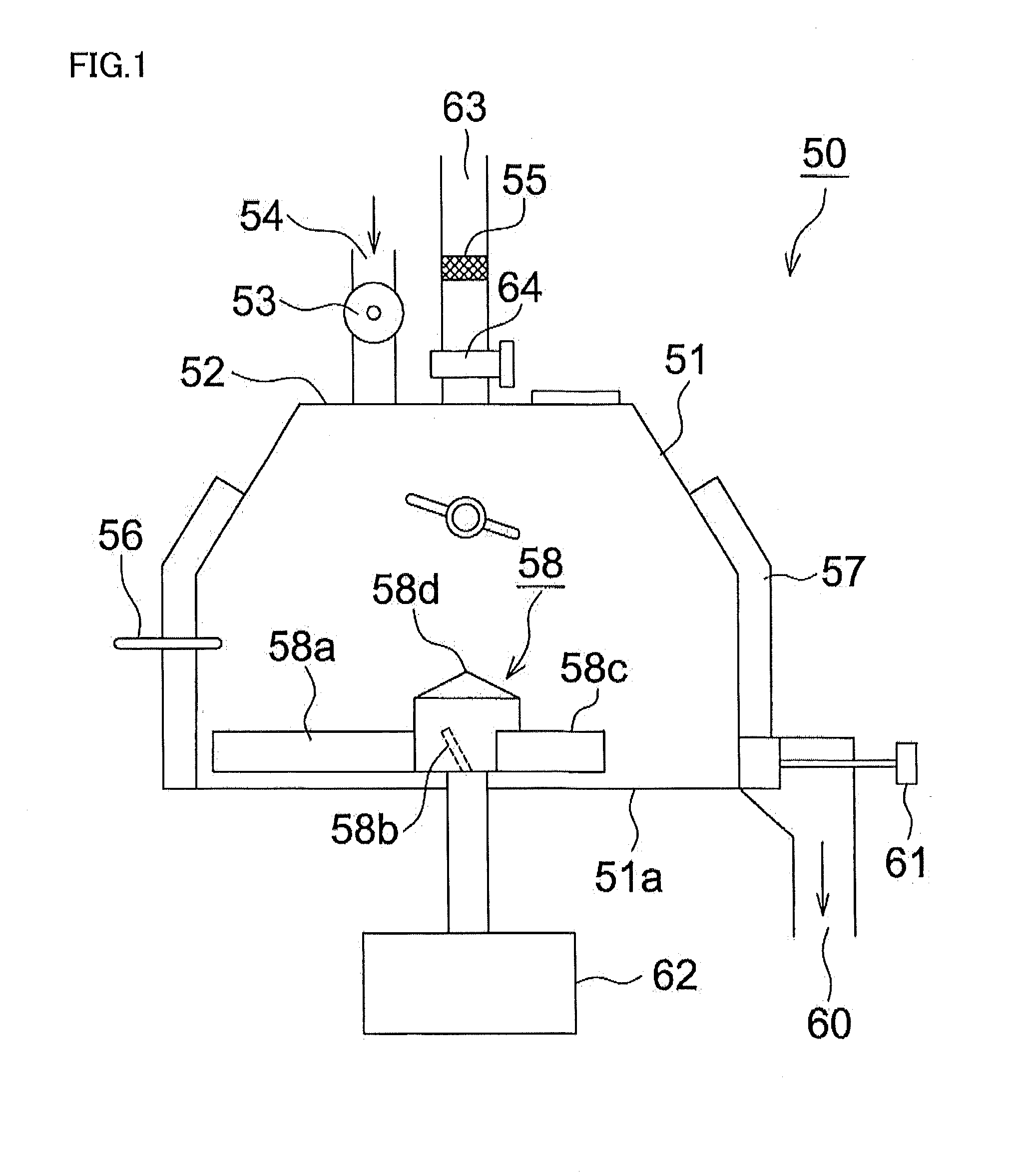
[0172]Silica particles were fabricated as additive particles 1 through a procedure below, with a sol-gel method. In a reaction vessel provided with a stirrer, a dropping funnel, and a thermometer,
[0173]625 parts by mass of methanol,
[0174]40 parts by mass of water, and
[0175]50 parts by mass of 28 mass % ammonia water were introduced, to thereby fabricate a methanol-water solvent mixture containing ammonia water. A temperature of the solvent mixture was adjusted to 35° C., and
[0176]800 parts by mass of tetramethoxysilane, and
[0177]420 parts by mass of 5.4 mass % ammonia water were each dropped in the solvent mixture above while stirring. Drop of these compounds was started simultaneously. Tetramethoxysilane was dropped for 3.5 hours and 5.4 mass % ammonia...
examples 2 to 18
, Comparative Examples 1 to 3
[0239]Developers were fabricated as in Example 1, except that pigments shown in Table 1 below were used as the first pigment, the second pigment, the third pigment, and the fourth pigment (some of which may contain other pigments) and an amount of addition (a ratio of addition) of each pigment was set as shown in Table 1. In any Example and Comparative Example, a total content of pigments in the toner particles was 15 mass %, as in Example 1.
TABLE 1FirstSecondThirdFourthOtherPigmentPigmentPigmentPigmentPigmentsExample 1CB1(50)BR1(30)C1(5)Y1(15)—Example 2CB1(52)BR2(40)C1(8)——Example 3CB2(60)BR1(40)———Example 4CB2(40)BR1(45)C2(10)Y1(5)—Example 5CB2(60)BR1(25)C1(4)Y1(11)—Example 6CB1(40)BR1(42)C1(10)Y2(8)—Example 7CB1(60)BR1(28)C1(2)Y3(10)—Example 8CB2(38)BR2(45)C1(11)Y1(6)—Example 9CB1(61)BR1(30)C1(5)Y4(4)—Example 10CB2(60)BR1(23)C1(8)Y1(9)—Example 11CB1(42)BR1(47)C2(10)Y1(2)—Example 12CB1(55)BR1(32)C1(1)Y2(12)—Example 13CB1(40)BR2(45)C1(12)Y2(3)—Example 1...
PUM
 Abstract
Description
Claims
Application Information
 - R&D
- Intellectual Property
- Life Sciences
- Materials
- Tech Scout
- Unparalleled Data Quality
- Higher Quality Content
- 60% Fewer Hallucinations
Browse by: Latest US Patents, China's latest patents, Technical Efficacy Thesaurus, Application Domain, Technology Topic, Popular Technical Reports.
© 2025 PatSnap. All rights reserved.Legal|Privacy policy|Modern Slavery Act Transparency Statement|Sitemap|About US| Contact US: help@patsnap.com


