Biaxial scanning mirror having resonant frequency adjustment

a scanning mirror and resonant frequency technology, applied in the field of microelectromechanical systems, can solve the problems of increasing the cost of mems devices, not easy to achieve a large amplitude/scanning angle for a large-area mirror plate mems device, etc., and achieves a large amplitude/scanning angle, large scanning angle, and increased damping force

Active Publication Date: 2011-12-01
HONG KONG APPLIED SCI & TECH RES INST
View PDF0 Cites 15 Cited by
  • Summary
  • Abstract
  • Description
  • Claims
  • Application Information

AI Technical Summary

Benefits of technology

[0010]As discussed above, a MEMS biaxial scanning mirror is typically driven at its resonant frequency to achieve a large scanning angle. However, there are many applications for MEMS scanning mirrors which require different resonant frequencies. Therefore, it is a desirable feature to have a flexible design for the MEMS scanning mirror to create devices with different resonant frequencies. For example, a scanning mirror for a touch panel application requires a low resonant frequency. Low resonant frequencies can be realized by large moments of inertia, typically via a large-area mirror plate. However, it is not easy to achieve a large amplitude / scanning angle for a large-area mirror plate MEMS device since the mirror plate suffers greater damping force during rotation. Further, large-area mirror plates increase the cost of MEMS devices.

Problems solved by technology

However, it is not easy to achieve a large amplitude / scanning angle for a large-area mirror plate MEMS device since the mirror plate suffers greater damping force during rotation.
Further, large-area mirror plates increase the cost of MEMS devices.

Method used


Image

  • Biaxial scanning mirror having resonant frequency adjustment
  • Biaxial scanning mirror having resonant frequency adjustment
  • Biaxial scanning mirror having resonant frequency adjustment

Examples


Embodiment Construction

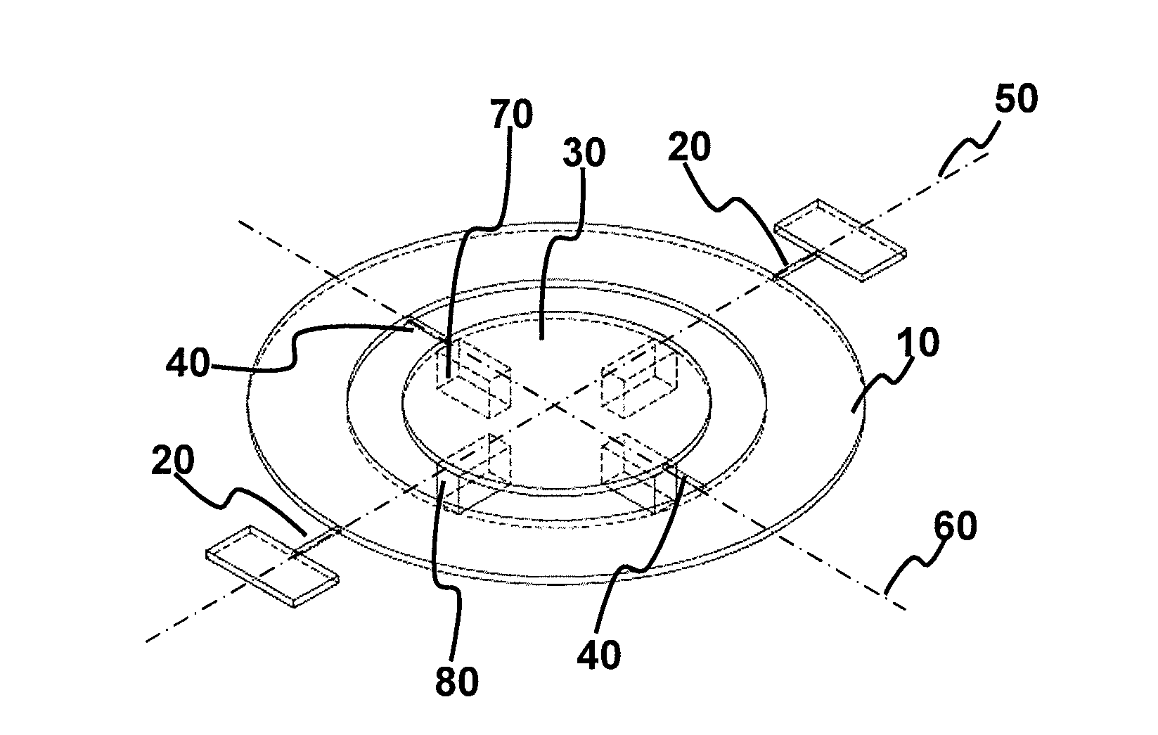
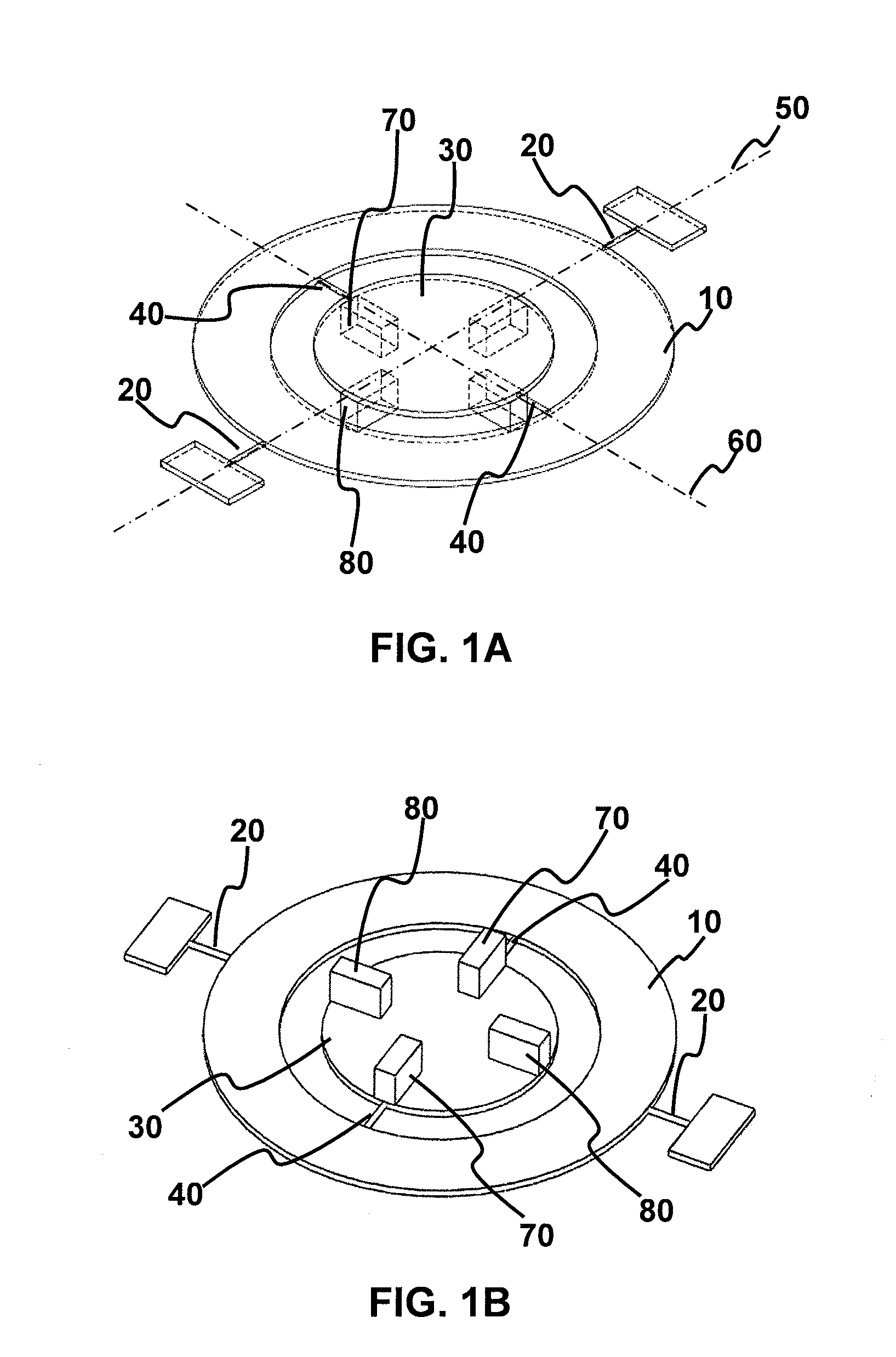
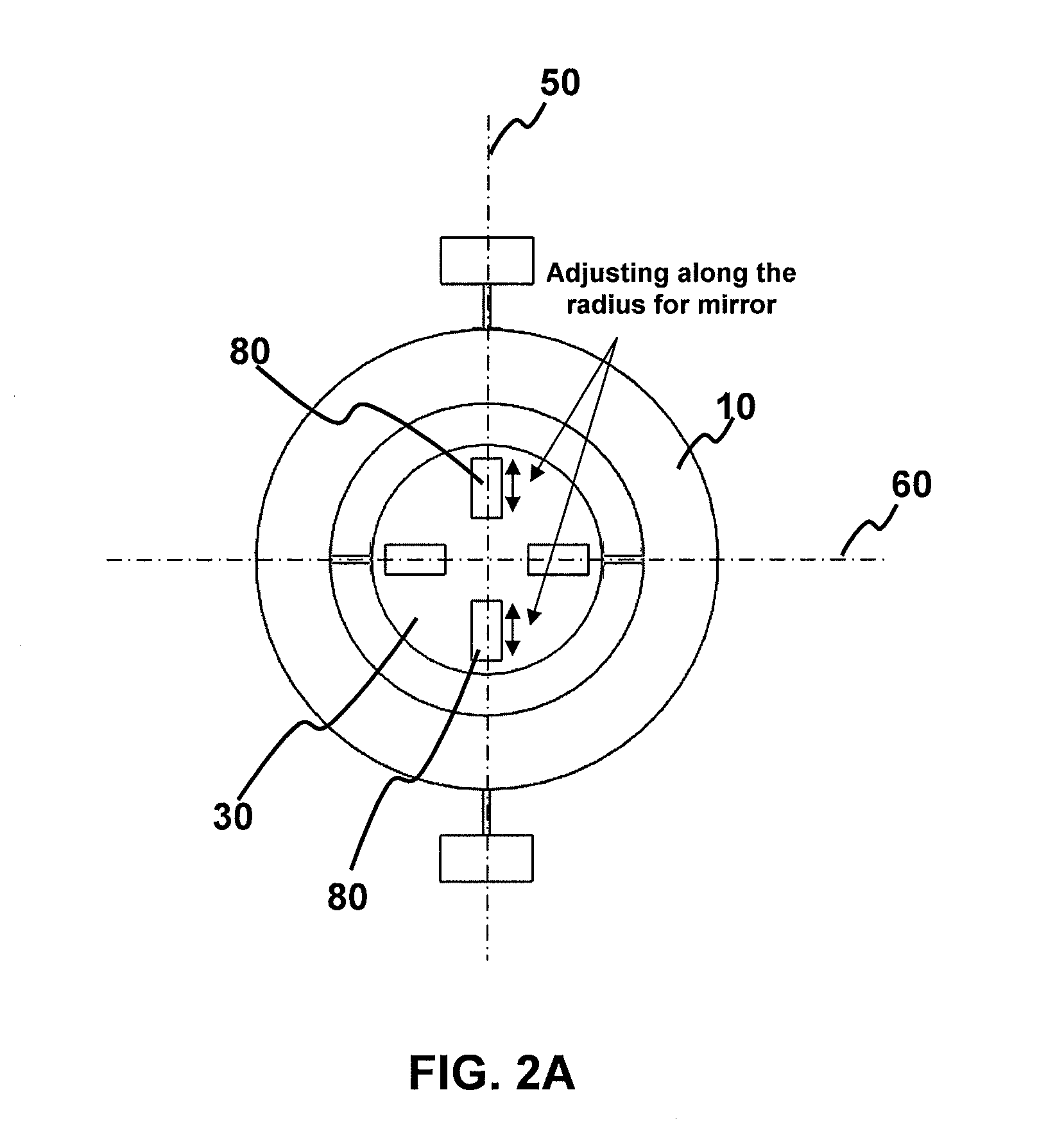
[0028]Turning now to the drawings in detail, FIGS. 1A and 1B show an embodiment of a biaxial MEMS structure. The principal features of the MEMS structure are gimbal 10, gimbal torsional bars 20, mirror plate 30, and mirror plate torsional bars 40. Gimbal 10 is rotated by gimbal torsional bars 20 about a gimbal axis of rotation 50. Similarly, mirror plate 20 is rotated by mirror plate torsional bars 40 about a mirror plate axis of rotation 60.

[0029]One or more blocks 70 and one or more blocks 80 are positioned underneath the mirror plate in order to affect the moment of inertia and, thereby, the resonant frequency of the mirror plate. Note that in the exemplary embodiments the blocks are positioned on the rear surfaces of the mirror plate and / or gimbal; however, the blocks may optionally be positioned on the front surfaces of the mirror plate and / or gimbal with the same effect. The effect of the blocks on the moment of inertia is explained as follows. In a rotation dynamic, the momen...


PUM


Abstract

A biaxial micro-electromechanical (MEMS) device is disclosed. The device includes a gimbal rotatable about a gimbal axis of rotation. A pair of gimbal torsion bars connects the gimbal to a support along the gimbal rotation axis. A mirror plate is rotatable about a mirror axis of rotation, the mirror plate rotation axis being substantially perpendicular to the gimbal rotation axis. A pair of mirror plate torsion bars connects the mirror plate to the gimbal along the mirror plate axis of rotation. One or more gimbal moment-of-inertia-altering blocks are positioned on a surface of the mirror plate away from the gimbal axis of rotation. Additionally, one or more mirror plate moment-of-inertia-altering blocks are positioned on a surface of the mirror plate away from the mirror plate rotation axis such that the distance from the mirror plate axis determines a resonant frequency of the biaxial MEMS device.

Description

FIELD OF THE INVENTION[0001]The invention relates to micro-electromechanical systems (MEMS) in general, and, more particularly, to adjustment of the resonant frequency of MEMS systems.BACKGROUND OF THE INVENTION[0002]MEMS scanning devices find application in a wide variety of electrical, mechanical, and optical systems. A non-exhaustive list of applications includes scanners, displays, projectors, switches, printers, barcode readers, retinal displays, resonators, and sensors. MEMS scanning devices may be driven by, for example, electrostatic actuation, electromagnetic actuation, a combination of electrostatic and electromagnetic actuation, and piezoelectric actuation.[0003]In scanning applications, MEMS devices are typically driven at their resonant frequencies to produce the desired scanning angle and scanning speed. When using a MEMS device as a mirror in a scanning device, the mirror size affects the resulting resonant frequency. If a large mirror size is used, it is difficult to...

Claims


Application Information

Patent Timeline
Patent Type & Authority Applications(United States)
IPC IPC(8): G02B26/10
CPCG02B7/1821G02B26/105G02B26/0841
Inventor MA, WEILEE, FRANCIS CHEE-SHUENCHAN, HO YIN
Owner HONG KONG APPLIED SCI & TECH RES INST
Why Eureka
Try Eureka