Webbing take-up device

a take-up device and webbing technology, applied in the direction of vehicle safety belts, belt retractors, vehicle components, etc., can solve the problem of generating (rattling) noise, and achieve the effect of suppressing (rattling) nois

Active Publication Date: 2011-12-22
KK TOKAI RIKA DENKI SEISAKUSHO
View PDF4 Cites 7 Cited by
  • Summary
  • Abstract
  • Description
  • Claims
  • Application Information

AI Technical Summary

Benefits of technology

[0015]In the webbing take-up device according to the second aspect, the abut surface of the clutch plate abutting (contacting) with the leading end section of the second arm section is directed to the direction opposite to the direction toward the clutch cover side and the engaged section side. Thus, the clutch plate can be urged by the L-shaped spring toward the c

Problems solved by technology

However, in the webbing take-up device disclosed in JP-A No. 2007-84042 mentioned above, in a case where clearances are formed between the second lock pawl and the second lock base and the circular plate in order to ensure a rotary movement o

Method used


Image

  • Webbing take-up device
  • Webbing take-up device
  • Webbing take-up device

Examples


Embodiment Construction

[0027]In the following, description is made of embodiments of the present invention with reference to figures.

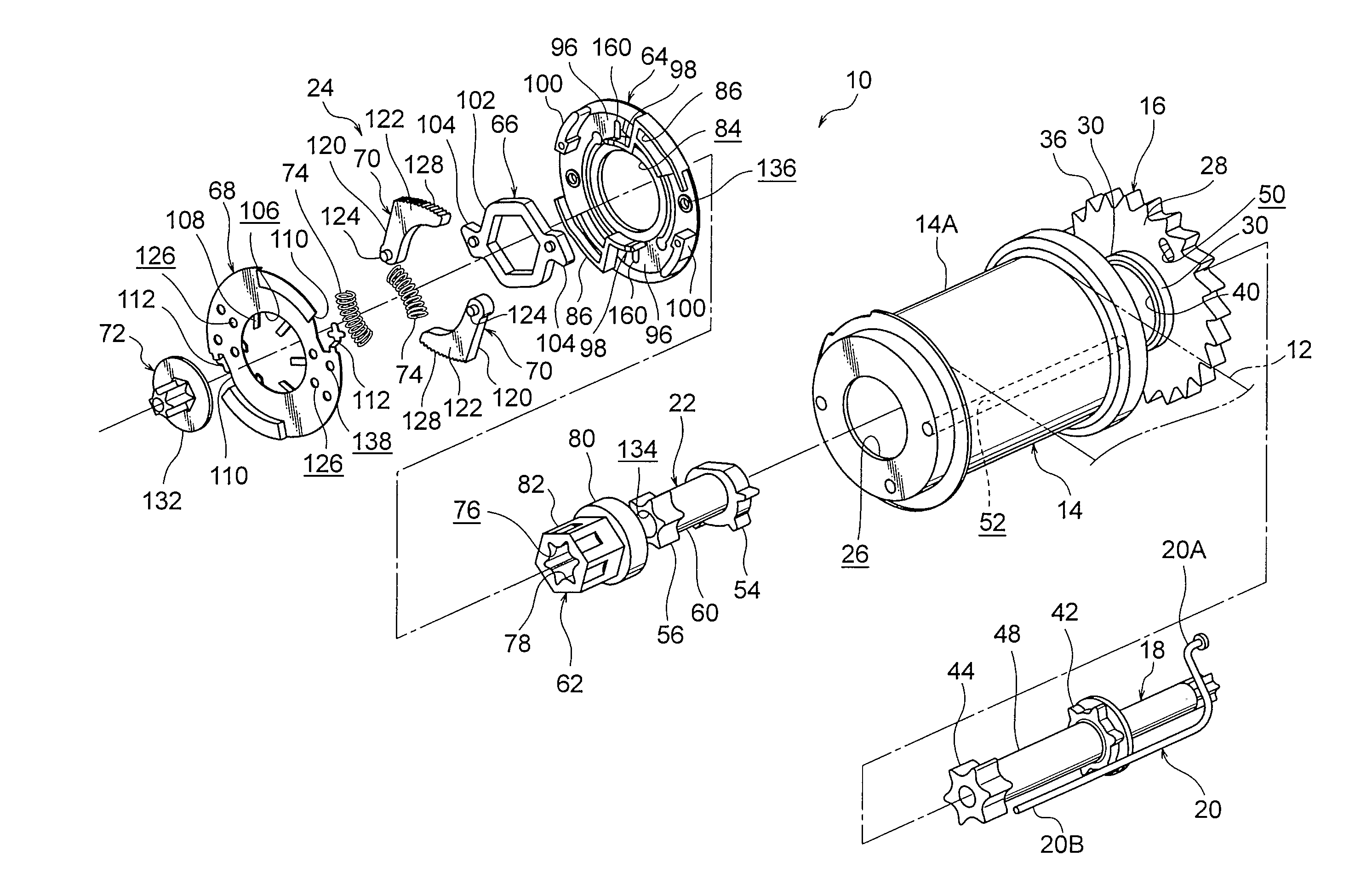
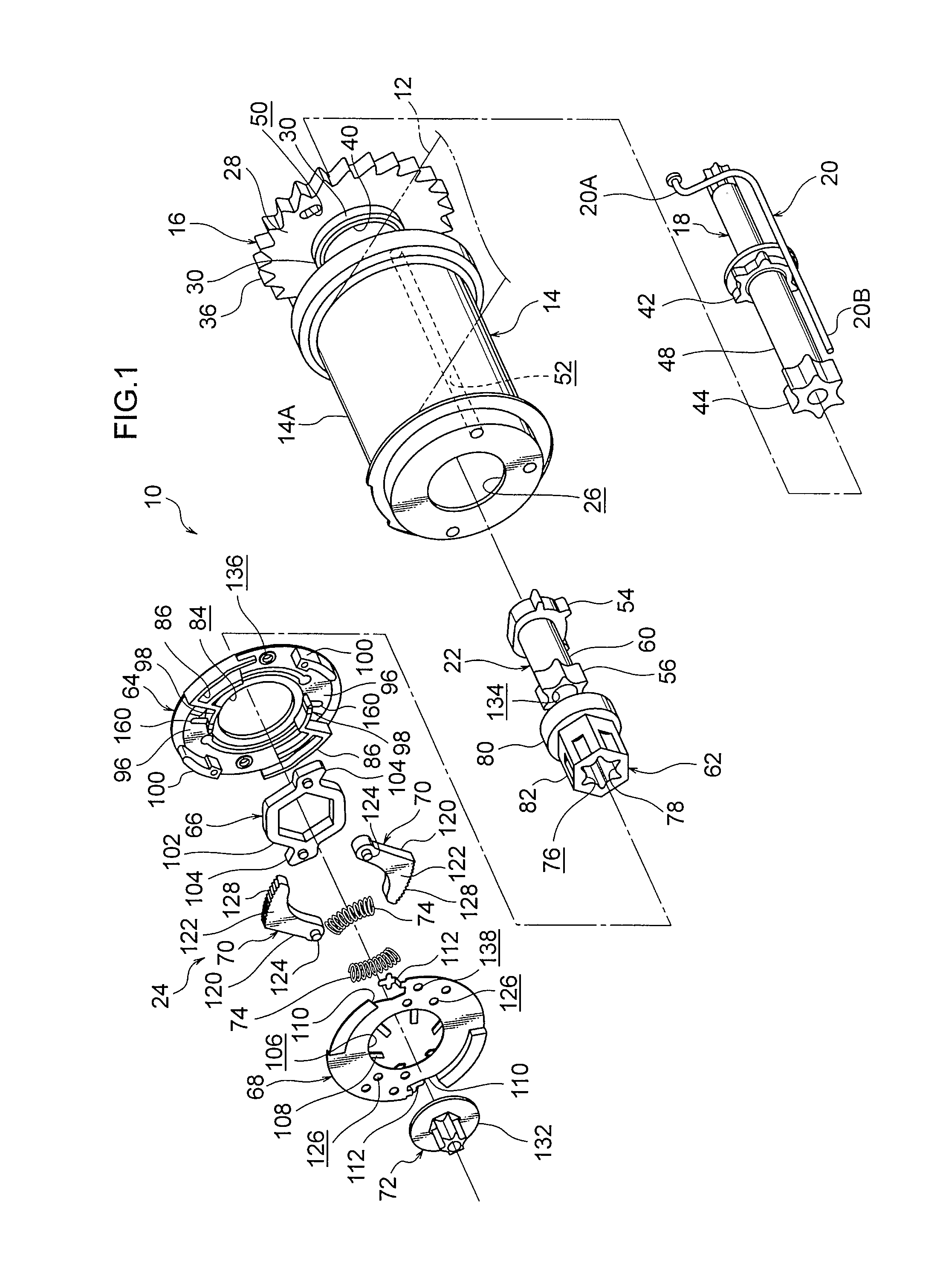
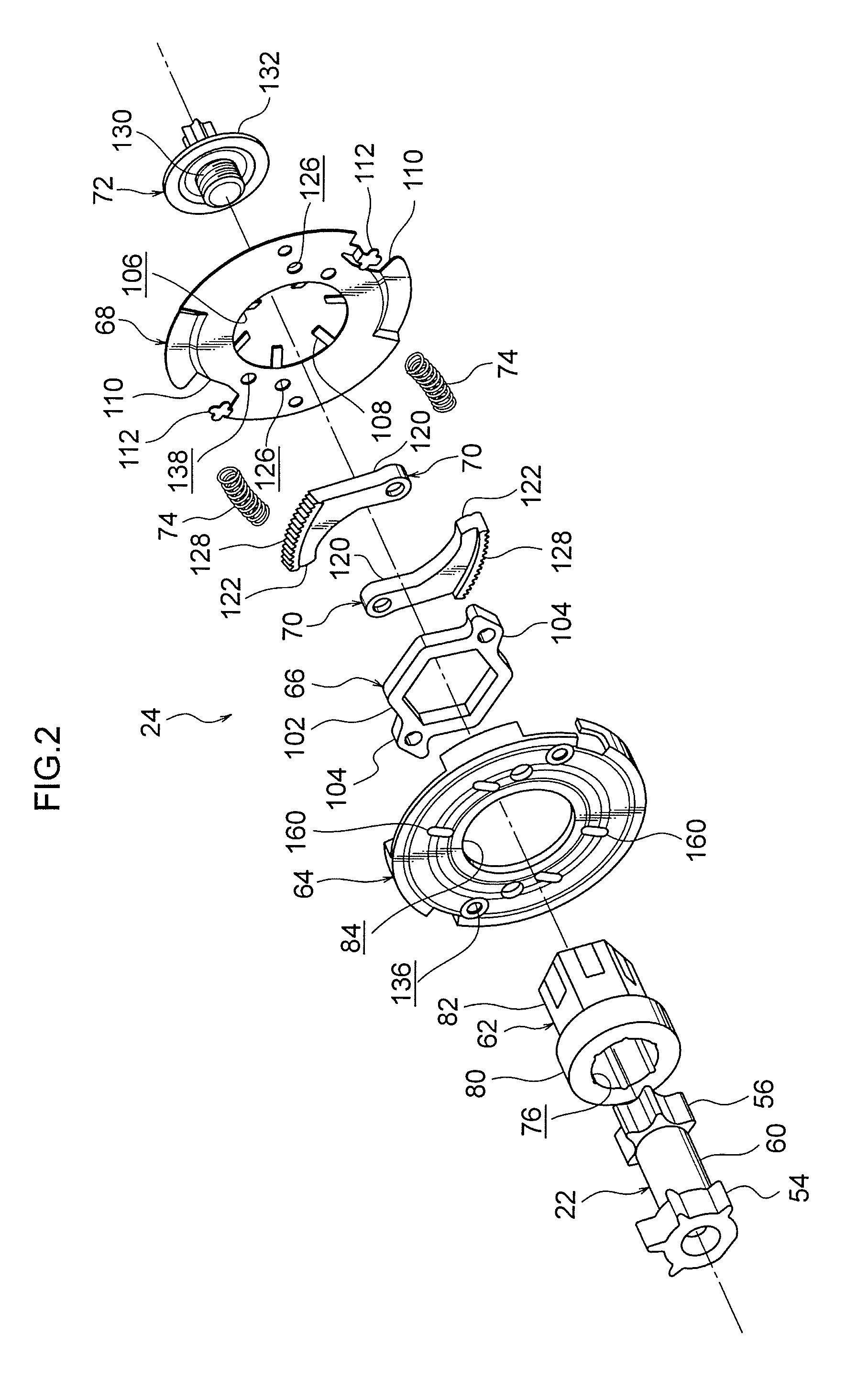
[0028]As illustrated in FIG. 1, a webbing take-up device 10 according to an embodiment of the present invention includes a webbing belt 12, a spool 14, a lock gear 16, a main torsion shaft 18, a trigger wire 20, a sub-torsion shaft 22, and a clutch mechanism 24.

[0029]The webbing belt 12 is applied to a passenger's body, and a proximal end section thereof is secured (caught or connected) to the spool 14. The spool 14 is formed in such a cylindrical shape as to include a through-hole 26 passing therethrough in an axial direction. When the spool 14 is rotated in a take-up direction as one rotational direction, the spool 14 takes up the webbing belt 12 around an outer peripheral section 14A.

[0030]The lock gear 16 is arranged coaxially with the spool 14 on one axial-direction side of the spool 14, and includes a gear body 28 and a projecting section 30 projecting from the gear bo...


PUM


Abstract

The present invention is to suppress a generation of a noise due to repeatedly hitting a clutch plate against a clutch cover and a clutch guide. A webbing take-up device is provided with a clutch cover fixed to a sub-torsion shaft so as to be rotatable integrally therewith; a clutch guide arranged so as to face the clutch cover, and supported capable of relatively rotating to the sub-torsion shaft; a lock ring formed around the clutch cover and the clutch guide; and a clutch plates turned to a lock ring side while being guided by the clutch guide in accordance with relative rotation of the clutch guide to the clutch cover into one rotational direction, and engaged with the lock ring. L-shaped springs which urge the clutch plates to a clutch cover side are formed integrally with the clutch guide.

Description

CROSS-REFERENCE TO RELATED APPLICATION[0001]This application claims priority under 35 USC 119 from Japanese Patent Application No. 2010-139982 filed Jun. 18, 2010, the disclosure of which is incorporated by reference herein.BACKGROUND OF THE INVENTION[0002]1. Field of the Invention[0003]The present invention relates to a webbing take-up device.[0004]2. Related Art[0005]In a webbing take-up device disclosed in Japanese Patent Application Laid-Open (JP-A) No. 2007-84042, a torsion shaft is fixed to a spool so as to be rotatable integrally therewith. On one end side of the torsion shaft, a second lock base is fixed so as to be integrally rotatable, and a circular plate is supported so as to be relatively rotatable.[0006]Second lock pawls are turnably supported by the second lock base, and guide pins projecting from the circular plate are movably engaged with elongated holes respectively formed in the second lock pawls.[0007]When a stopper which regulates a relative rotation of the seco...

Claims


Application Information

Patent Timeline
IPC IPC(8): B60R22/34B60R22/46
CPCB60R22/341B60R2022/287B60R22/38
Inventor YANAGAWA, WATARUUKITA, MASARUMAEKUBO, YOSHIAKI
Owner KK TOKAI RIKA DENKI SEISAKUSHO
Why Eureka
Try Eureka