
Storage device for vehicle

a storage device and vehicle technology, applied in the direction of passenger space, roofs, transportation and packaging, etc., can solve the problems of inability to secure durability and easy generation of abnormal noise, and achieve the effect of suppressing the falling of an article through the lighting window and reducing costs

Active Publication Date: 2013-06-06
HONDA MOTOR CO LTD
View PDF0 Cites 5 Cited by
  • Summary
  • Abstract
  • Description
  • Claims
  • Application Information

AI Technical Summary

Benefits of technology

The present invention provides a storage device for a vehicle that can suppress abnormal noise during running of the vehicle and improve durability. The storage device employs a separator that is engaged with engagement holes on the back side of the storage section to secure mounting rigidity. The separator is formed in a L shape, making it highly rigid. The engagement holes are engaged with opposite projecting portions of the sepapar, reducing the number of engagement holes required and simplifying the shape of the storage section. The locking claws on the projecting portions of the sepapar are formed in opposite directions, simplifying the engagement with the storage section. The storage device includes a light source and a slit through which light can be penetrated, improving cost-effectiveness and preventing article falling.

Problems solved by technology

In the structure described above, during running of a vehicle, the partitioning tubular body moves, and thus abnormal noise is prone to be generated.
Further, if the storage form is repeatedly changed, breakage easily occurs, and thus there is a possibility that durability cannot be secured.

Method used


Image

  • Storage device for vehicle
  • Storage device for vehicle
  • Storage device for vehicle

Examples


first embodiment

[0040]A storage device for a vehicle related to the invention will be described below with reference to FIGS. 1 to 15.

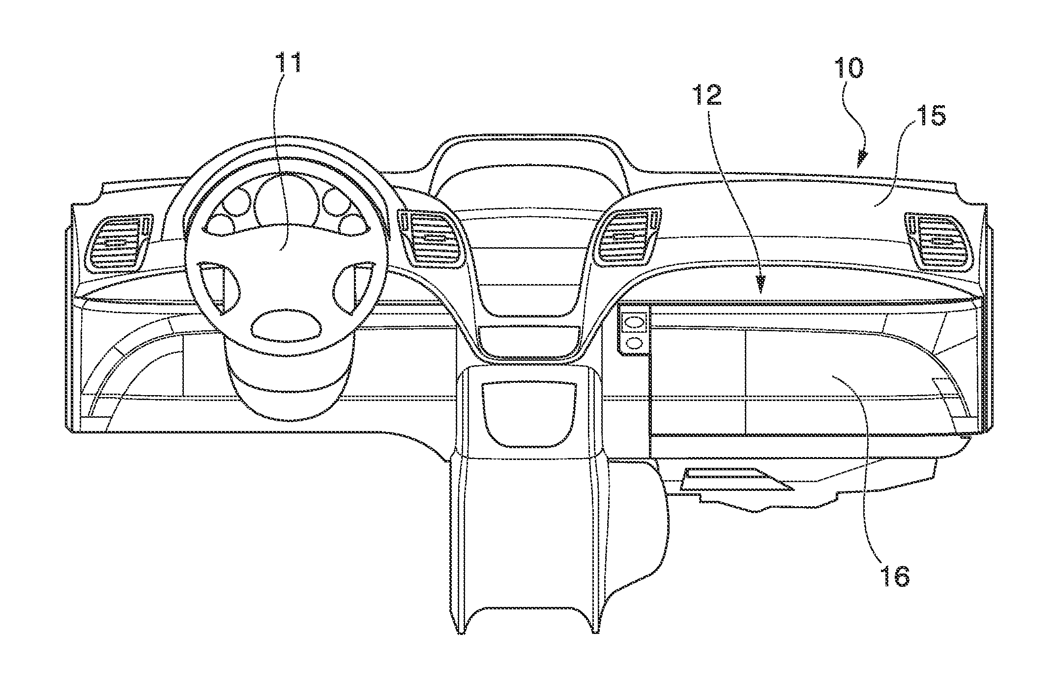
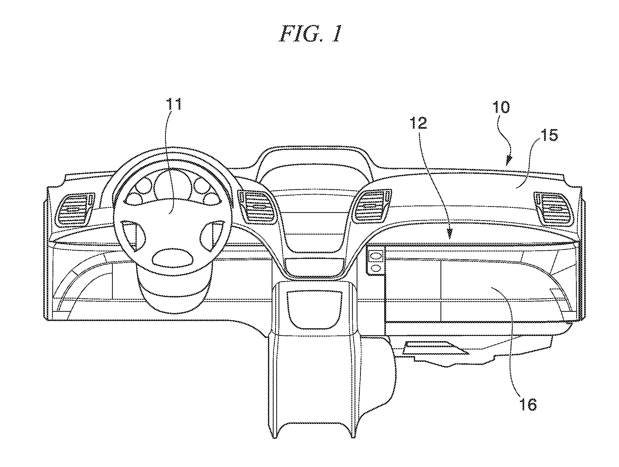
[0041]FIG. 1 shows an instrument panel 10 of a vehicle. As shown in FIG. 1, a storage device for a vehicle 12 related to the first embodiment is provided on the opposite side to a steering wheel 11 in the vehicle width direction (the left-and-right direction in FIG. 1) of the instrument panel 10, that is, on the front passenger seat side. That is, the storage device for a vehicle 12 is a glove box.

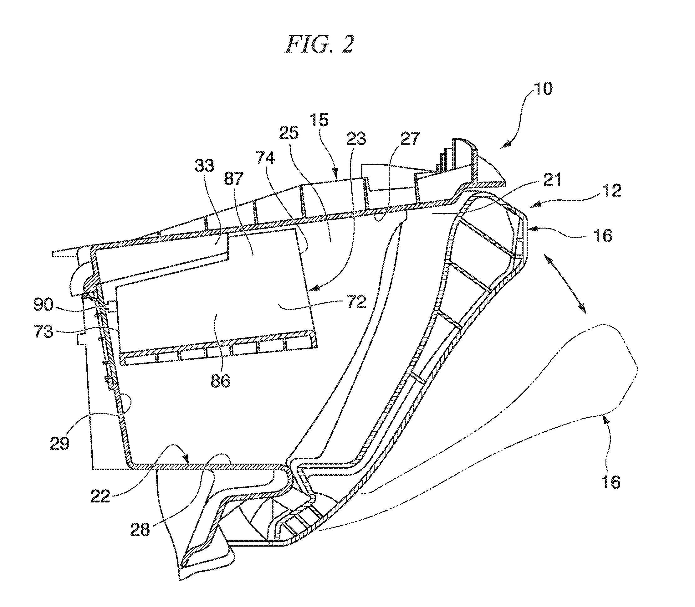
[0042]The instrument panel 10 has an instrument panel main body 15 and a lid 16 disposed on the opposite side to the steering wheel 11 of the instrument panel main body 15. The lid 16 is provided on the rear side (the right side in FIG. 2) in the vehicle front-and-back direction of the instrument panel main body 15 and supported on the instrument panel main body 15 so as to be able to swing around a lower portion of the instrument panel main body 15, as shown in FIG. 2.

[004...

second embodiment

[0079]As shown in FIG. 16, in the storage device for a vehicle 12 related to the second embodiment, a light source 101 is provided at the sidewall surface section 25 of the storage section 22. The light source 101 illuminates the storage section 22 in an irradiation direction which is directed to the sidewall surface section 26 on the opposite side to the sidewall surface section 25 in the vehicle width direction. The position of the light source 101 is aligned with the position of the plate section 72 of the separator 23 which is disposed at the partitioning position, in a direction connecting the ceiling surface section 27 and the bottom surface section 28 of the storage section 22. The light source 101 faces the plate section 72 and emits light toward the plate section 72.

[0080]As shown in FIG. 17, in the plate section 72 of the separator 23, a plurality of slits 105 extending in a direction perpendicular to the plate section 71 is formed (specifically, at five locations). The sl...


PUM


Abstract

A storage device for a vehicle includes a storage section which has a space and has an engagement hole provided on the back side in a mounting direction and in which an article is put in and taken out through an opening portion, and a detachable separator which partitions the space in the storage section, is formed in a substantially L shape having two plate sections intersecting one another when viewed from the mounting direction into the storage section, has a projecting portion which protrudes toward the front in the mounting direction and is engaged with the engagement hole, and is mounted in the engagement hole at a partitioning position to divide the space into two compartments and a compartment expanding position to form a single compartment larger than either of the two compartments in the space.

Description

BACKGROUND OF THE INVENTION[0001]1. Field of the Invention[0002]The present invention relates to a storage device for a vehicle, which is provided in a vehicle such as a four-wheeled vehicle.[0003]Priority is claimed on Japanese Patent Application No. 2011-263602 filed on Dec. 1, 2011 and Japanese Patent Application No. 2012-096617 filed on Apr. 20, 2012, the contents of which are incorporated herein by reference.[0004]2. Description of Related Art[0005]There is known a storage device in which a partitioning tubular body is provided in a glove box for an automobile so as to be able to be moved up and down, whereby the inside is partitioned at different vertical positions by the partitioning tubular body, thereby changing a storage form. In this glove box, both basal plates are stuck to both sidewall plates and the partitioning tubular body is supported by both basal plates through thin-walled hinge sections and parallel hinge sections, whereby the partitioning tubular body is made t...

Claims


Application Information

Patent Timeline
IPC IPC(8): B60R7/06
CPCB60Q3/022B60R7/06B60Q3/225
Inventor SAKAI, YOSHIHIROSAITOH, YUJIOKUNO, JUNPEI
Owner HONDA MOTOR CO LTD
Learn More