
Strand mountable antenna enclosure for wireless communication access system

a wireless communication access system and antenna enclosure technology, applied in the field of wireless communication access systems and strand mountable antennas, can solve the problems of aesthetic objections of the community, and the difficulty of operators in securing necessary sites, and achieve the effect of reducing the number of antennas and antenna details

Inactive Publication Date: 2011-12-22
PUBLIC WIRELESS
View PDF3 Cites 32 Cited by
  • Summary
  • Abstract
  • Description
  • Claims
  • Application Information

AI Technical Summary

Benefits of technology

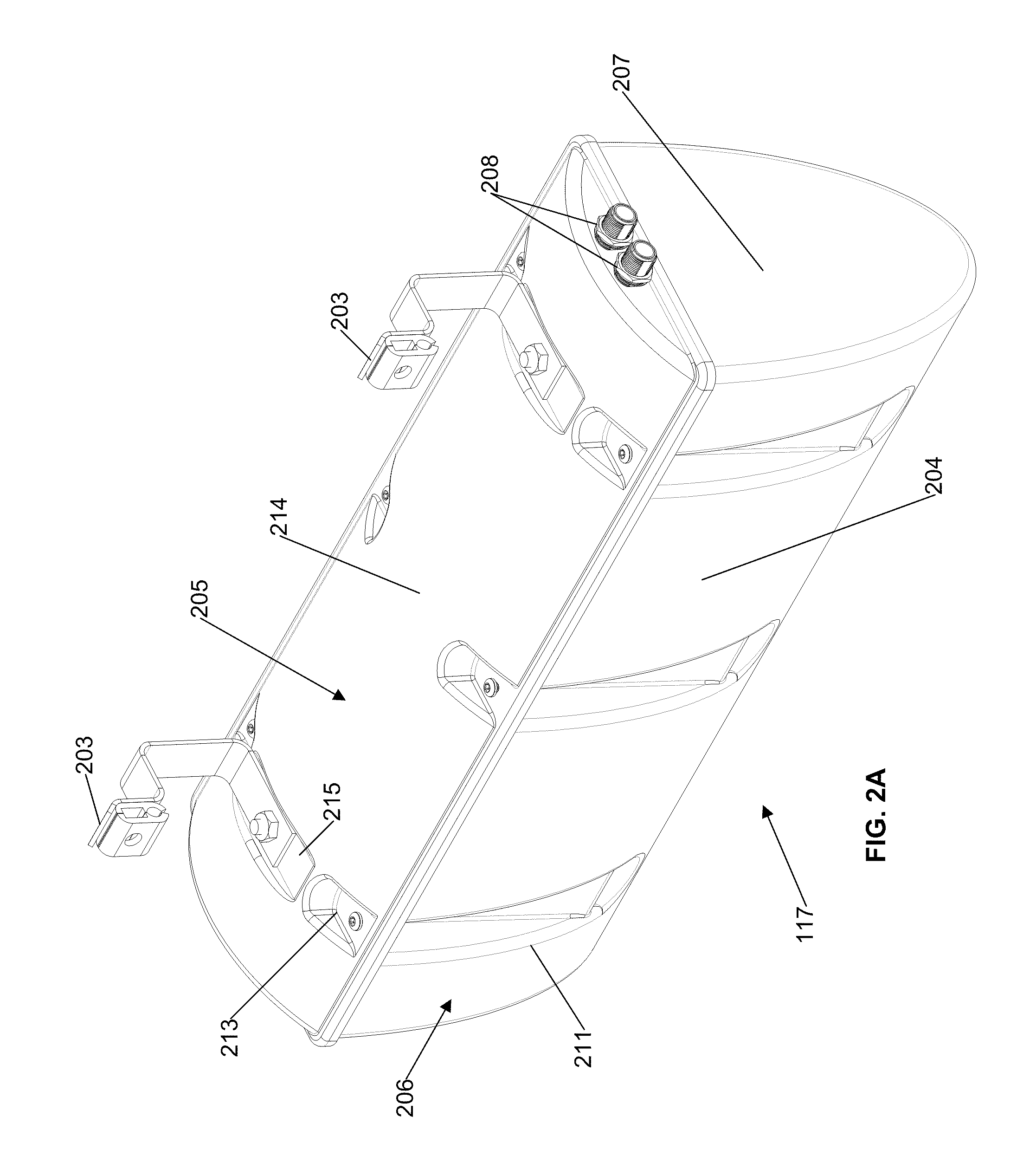
[0012]In one embodiment, the antenna enclosure comprises a base having an open top and a cover secured over the open top of the base. A ground plane may be secured in the enclosure over the open top of the base with the antenna element or elements secured to the ground plane and suspended in the base beneath the ground plane. There may be one, two, or three or more antenna elements in the enclosure. Other components or antenna circuitry may be mounted in the space between the ground plane and inner surface of the cover. One or more coaxial cable connectors may be provided on the enclo

Problems solved by technology

Building and deployment of new towers and antennas can give rise to aesthetic objections from the community.
Thus, it can be difficult for operators to secure necessary sites for locating base stations, repeaters, and associated antennas which make up wireless communication access systems.

Method used


Image

  • Strand mountable antenna enclosure for wireless communication access system
  • Strand mountable antenna enclosure for wireless communication access system
  • Strand mountable antenna enclosure for wireless communication access system

Examples


Embodiment Construction

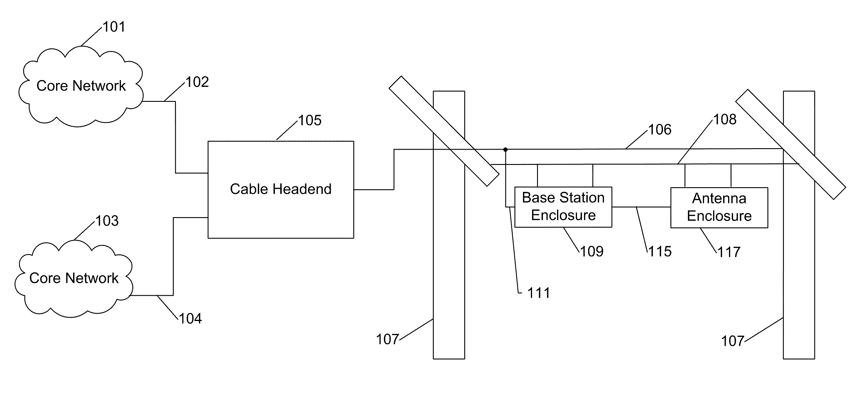
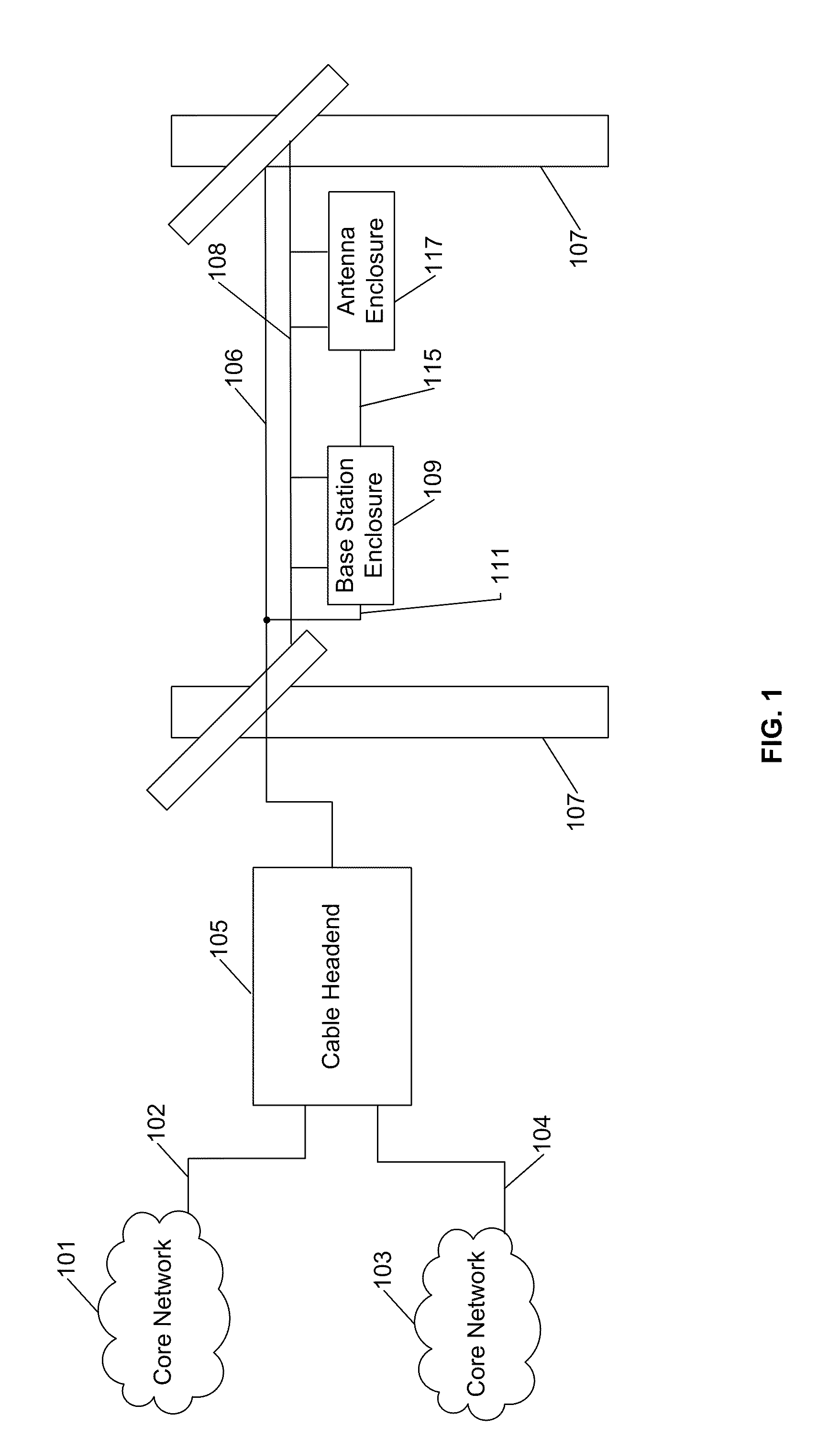
[0033]Certain embodiments as disclosed herein provide for a strand mountable antenna enclosure which blends in aesthetically with other strand mounted components and equipment.

[0034]After reading this description it will become apparent to one skilled in the art how to implement the invention in various alternative embodiments and alternative applications. However, although various embodiments of the present invention will be described herein, it is understood that these embodiments are presented by way of example only, and not limitation. As such, this detailed description of various alternative embodiments should not be construed to limit the scope or breadth of the present invention.

[0035]The systems and methods disclosed herein can be applied to various communication systems including various wireless technologies. For example, the systems and methods disclosed herein can be used with Cellular 2G, 3G, 4G (including Long Term Evolution (“LTE”), LTE Advanced, WiMax), and other wir...


PUM


Abstract

An antenna enclosure is designed to be suspended from a line such as a messenger strand which extends in a first direction between a pair of utility poles, in a similar manner to other aerial strand mounted communication system components. At least one antenna element is mounted in the enclosure. The antenna enclosure in one example is elongated in the first direction and tapers inwardly in a vertical direction between the upper and lower ends of the enclosure. Two spaced connecting brackets mounted on the upper end of the enclosure are configured for connection to spaced positions on a line to suspend the enclosure from the line.

Description

RELATED APPLICATION[0001]The present application claims the benefit of co-pending U.S. provisional pat. App. Ser. No. 61 / 356,972 filed Jun. 21, 2010, the contents of which are incorporated herein by reference in their entirety.BACKGROUND[0002]1. Field of the Invention[0003]The present invention relates generally to the field of communication systems and more specifically to wireless communication access systems and strand mountable antennas for such systems.[0004]2. Related Art[0005]Operators of wireless or cellular communication networks typically use large towers and antennas to cover most of a desired coverage area for the communication system. Building and deployment of new towers and antennas can give rise to aesthetic objections from the community. Thus, it can be difficult for operators to secure necessary sites for locating base stations, repeaters, and associated antennas which make up wireless communication access systems.[0006]It is known to use existing aerial strand inf...

Claims


Application Information

Patent Timeline
IPC IPC(8): H01Q1/42
CPCH01Q1/24H01Q1/42
Inventor ABUMRAD, JAMESHAAS, ROGER
Owner PUBLIC WIRELESS
Learn More