Carbon canister

a carbon canister and carbon technology, applied in the field of evaporative control system, can solve the problems of increasing the loading weight of activated charcoal in the carbon canister, increasing the size of the carbon canister, and the type of adsorption of fuel vapor, so as to reduce or at least minimize the escape of fuel vapor. effect of adsorption

Inactive Publication Date: 2011-12-29
MAHLE FILTER SYST JAPAN CORP
View PDF5 Cites 52 Cited by
  • Summary
  • Abstract
  • Description
  • Claims
  • Application Information

AI Technical Summary

Benefits of technology

[0006]In the carbon canisters disclosed by the above-mentioned Japanese Publications, ideas are embodied in the carbon canister for suppressing or at least minimizing undesired escape of fuel vapors from the carbon canister into

Problems solved by technology

When considering such purpose, it can be easily recognized that the activated charcoal used as the adsorbing material is of a type that is somewhat poor in fuel vapor adsorbing ability.
Thus, when, under such condition, combination of the ability of trapping (or adsorbing) fuel vapors by the activated charcoal and the ability of clearing the trapped fuel vapor from the activated charcoal is required, there is no way except the way of increasing the loading weight of the activated charcoal in the carbon canister.
However, in this case, the carbon cani

Method used


Image

  • Carbon canister
  • Carbon canister
  • Carbon canister

Examples


first embodiment

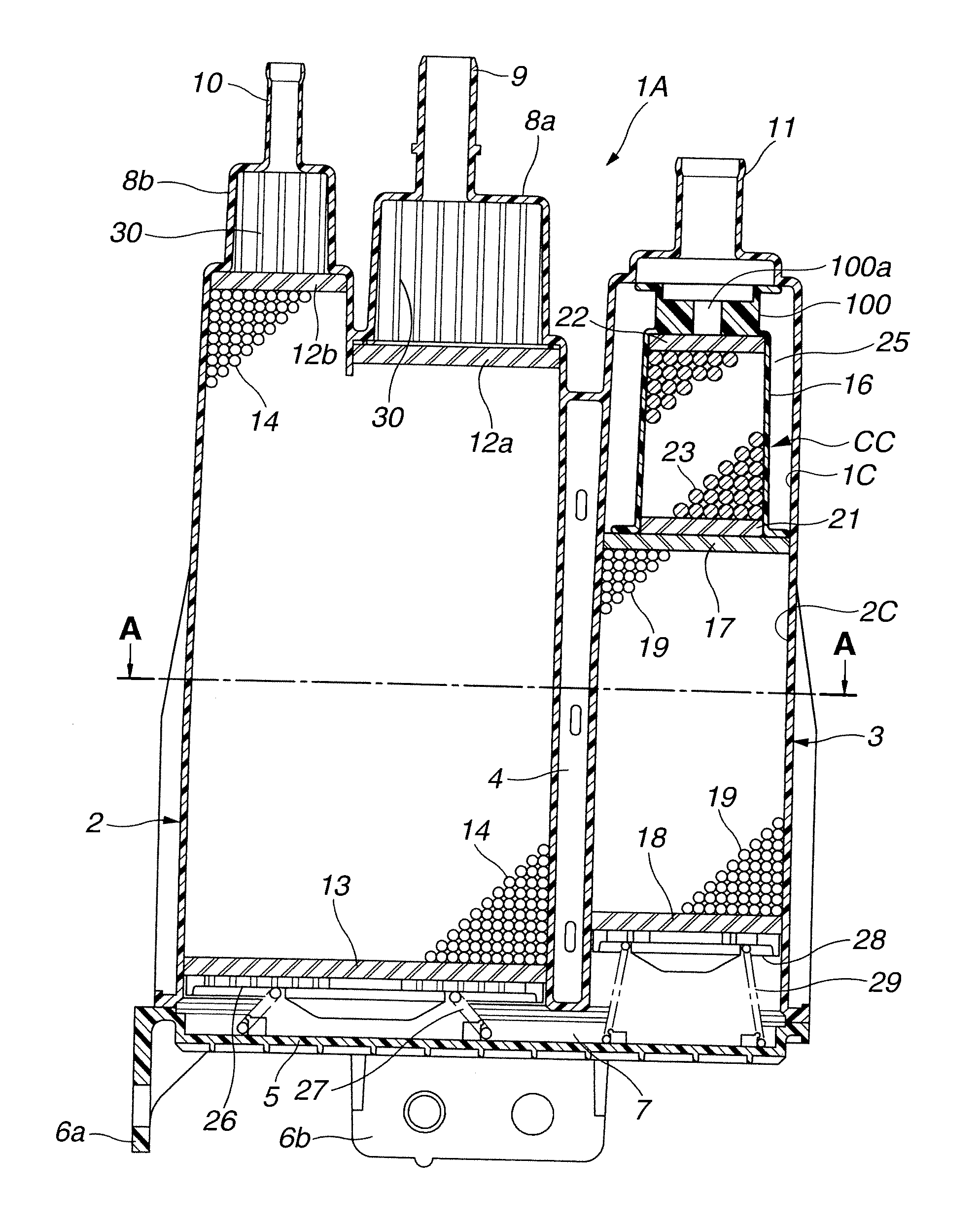
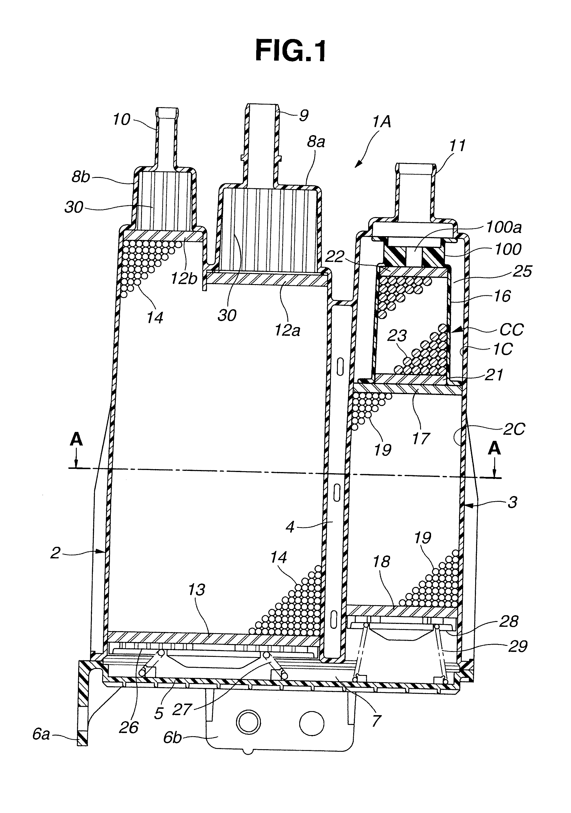
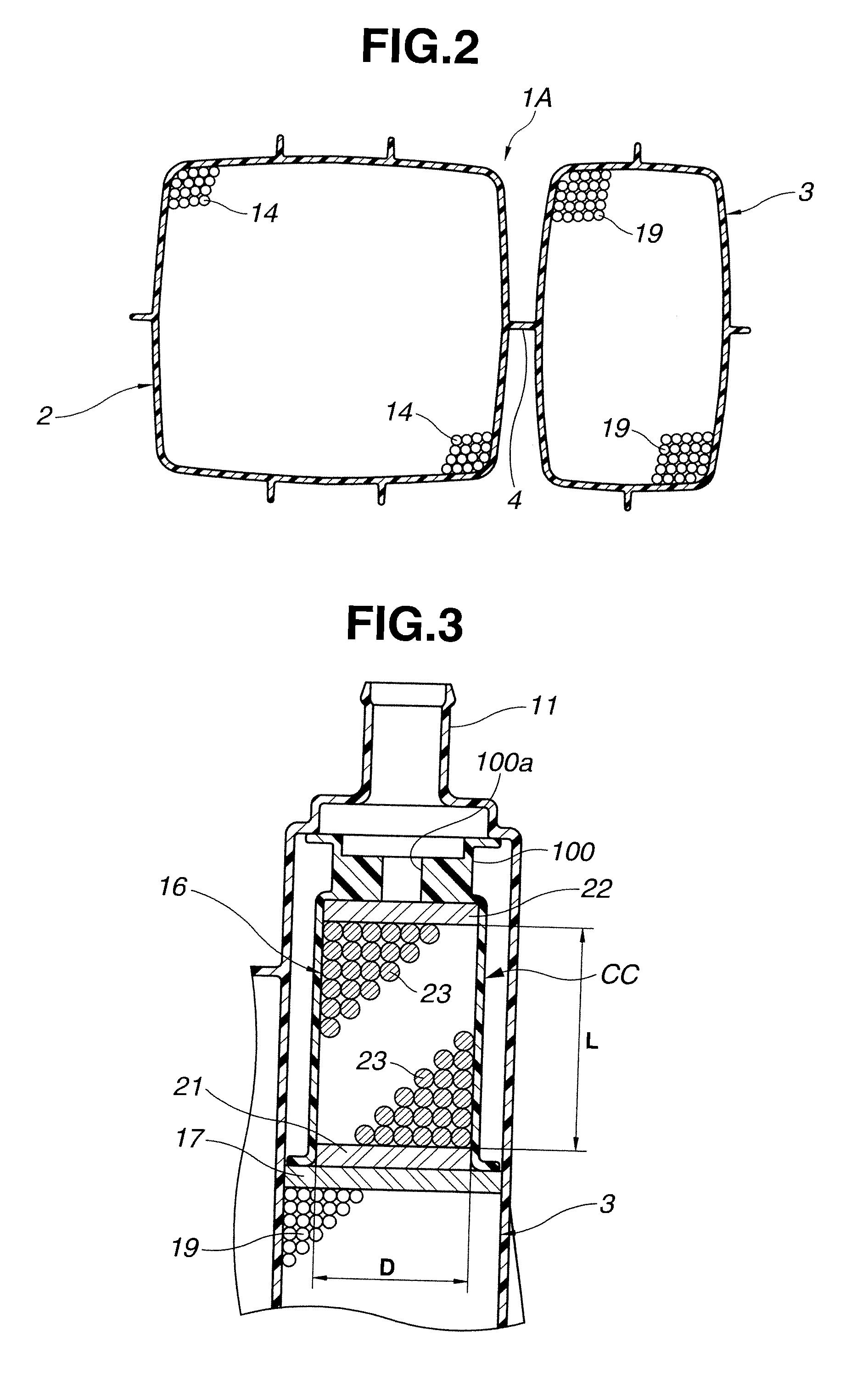
[0021]Referring to FIGS. 1, 2 and 3, particularly FIG. 1, there is shown a carbon canister 1A of the present invention.

[0022]As is seen from FIG. 1, the carbon canister 1A, more specifically, a casing of the carbon canister 1A, is made of a molded plastic such as molded polyamide resin or the like.

[0023]That is, the carbon canister 1A comprises generally a first casing part 2 that is shaped into a larger rectangular parallelepiped form and a second casing part 3 that is shaped into a smaller rectangular parallelepiped form.

[0024]As is understood from FIGS. 1 and 2, the first and second casing parts 2 and 3 are united together through a lib structure 4 formed therebetween.

[0025]Referring back to FIG. 1, located below the first and second casing parts 2 and 3 is a lower cover plate 5 that is bonded to lower portions of the casing parts 2 and 3 by a known adhesive. The lower cover plate 5 is made of a molded plastic, such as molded polyamide resin or the like.

[0026]With provision of th...


PUM


Abstract

In a carbon canister including a casing with first and second casing parts connected through a passage, a first type of granulated adsorbing material 14, 19 packed in the first and s second casing parts, a charge port pipe 9 connected to the first casing part, a purge port pipe 10 connected to the first casing part, an air inlet pipe 11, 34 fluidly connected to the second casing part, there is provided an additional carbon canister section CC, 32 between the air inlet pipe 11,34 and the second casing, the additional carbon canister section containing therein a second type of granulated adsorbing material 23 of which fuel vapor adsorbing/clearing ability is equal to or higher than that of the first type of granulated adsorbing material 14, 19.

Description

BACKGROUND OF THE INVENTION[0001]1. Field of the Invention[0002]The present invention relates in general to an evaporative control system of a motor vehicle powered by fuel such as gasoline or the like, and more particularly to a carbon canister installed in the evaporative control system, which adsorbs fuel vapor from a fuel tank of the motor vehicle and when the engine starts, feeds the fuel vapor to the engine with the aid of fresh air flowing through the carbon canister.[0003]2. Description of the Related Art[0004]As is known, in current motor vehicles powered by fuel such as gasoline or the like, there is equipped a carbon canister is that captures the fuel vapors from the fuel tank and prevents them from escaping into the atmosphere. That is, when the engine shuts off, fuel vapors flow from the fuel tank into the carbon canister. The activated charcoal in the carbon canister traps or adsorbs the fuel vapors. Later, when the engine starts, fresh air flows through the carbon can...

Claims


Application Information

Patent Timeline
IPC IPC(8): F02M33/02
CPCF02M25/0854
Inventor YOSHIDA, HIROYUKIHASUMI, TAKASHI
Owner MAHLE FILTER SYST JAPAN CORP
Why Eureka
Try Eureka