Ophthalmic lens, systems and methods with angular varying phase delay

a phase delay and angular variable technology, applied in the field of ophthalmic lenses, can solve the problems of reduced contrast vision, halos and glare of diffractive multifocal/bifocal iols, and achieve the effect of improving the performance of diffractive lenses

a phase delay and angular variable technology, applied in the field of ophthalmic lenses, can solve the problems of reduced contrast vision, halos and glare of diffractive multifocal/bifocal iols, and achieve the effect of improving the performance of diffractive lenses

US20110317124A1Active Publication Date: 2011-12-29AMO GRONINGEN

Image

  • Ophthalmic lens, systems and methods with angular varying phase delay
  • Ophthalmic lens, systems and methods with angular varying phase delay
  • Ophthalmic lens, systems and methods with angular varying phase delay

Examples


Embodiment Construction

[0031]It is to be understood that the figures and descriptions of the present invention have been simplified to illustrate elements that are relevant for a clear understanding of the present invention, while eliminating, for the purpose of clarity, many other elements found in typical lenses, lens systems and methods. Those of ordinary skill in the pertinent arts may recognize that other elements and / or steps are desirable and / or required in implementing the present invention. However, because such elements and steps are well known in the art, and because they do not facilitate a better understanding of the present invention, a discussion of such elements and steps is not provided herein. The disclosure herein is directed to all such variations and modifications to such elements and methods known to those skilled in the pertinent arts.

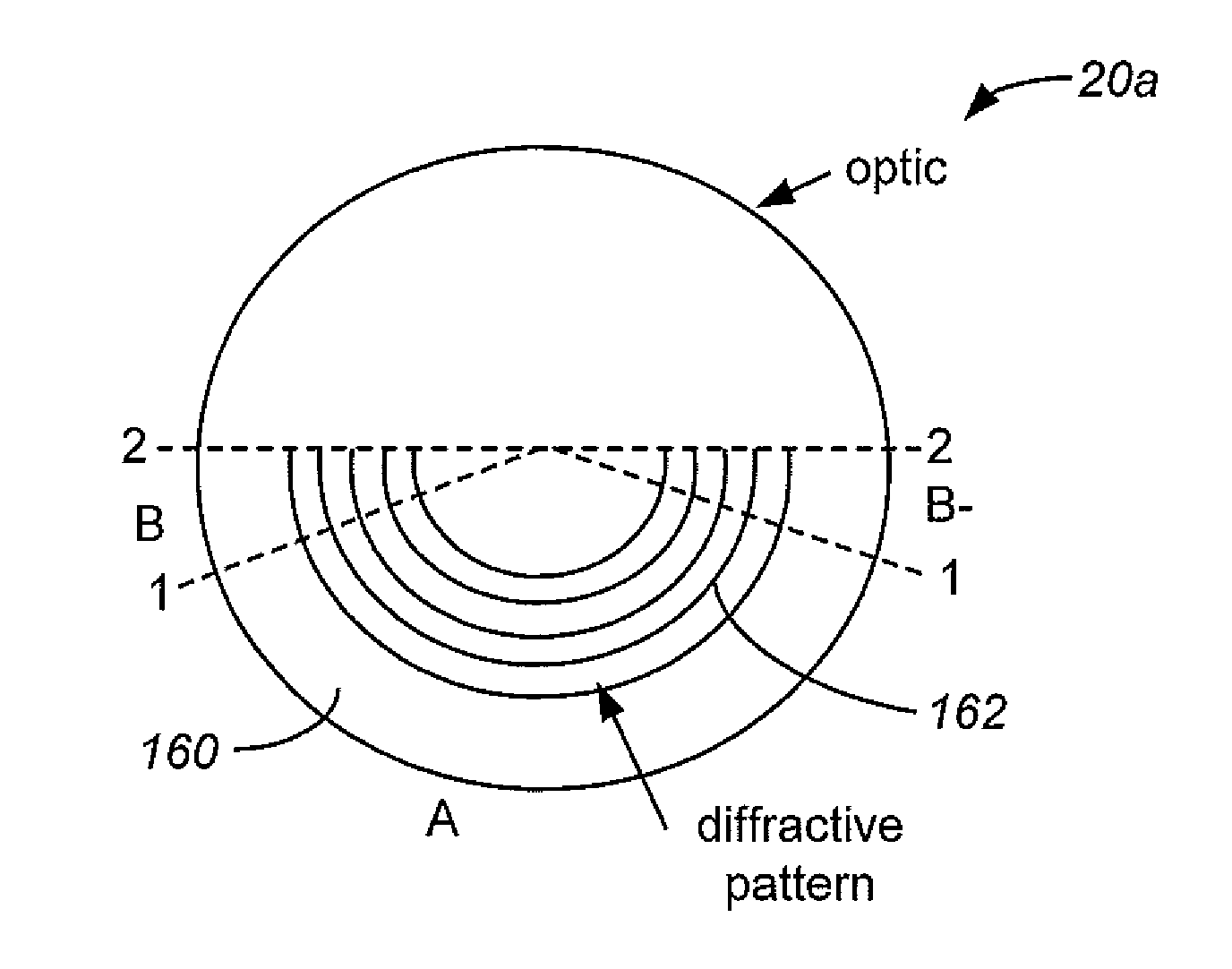
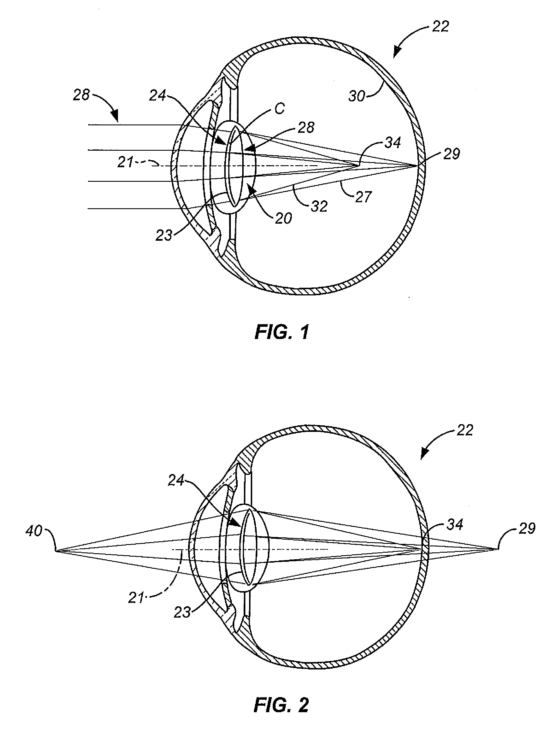
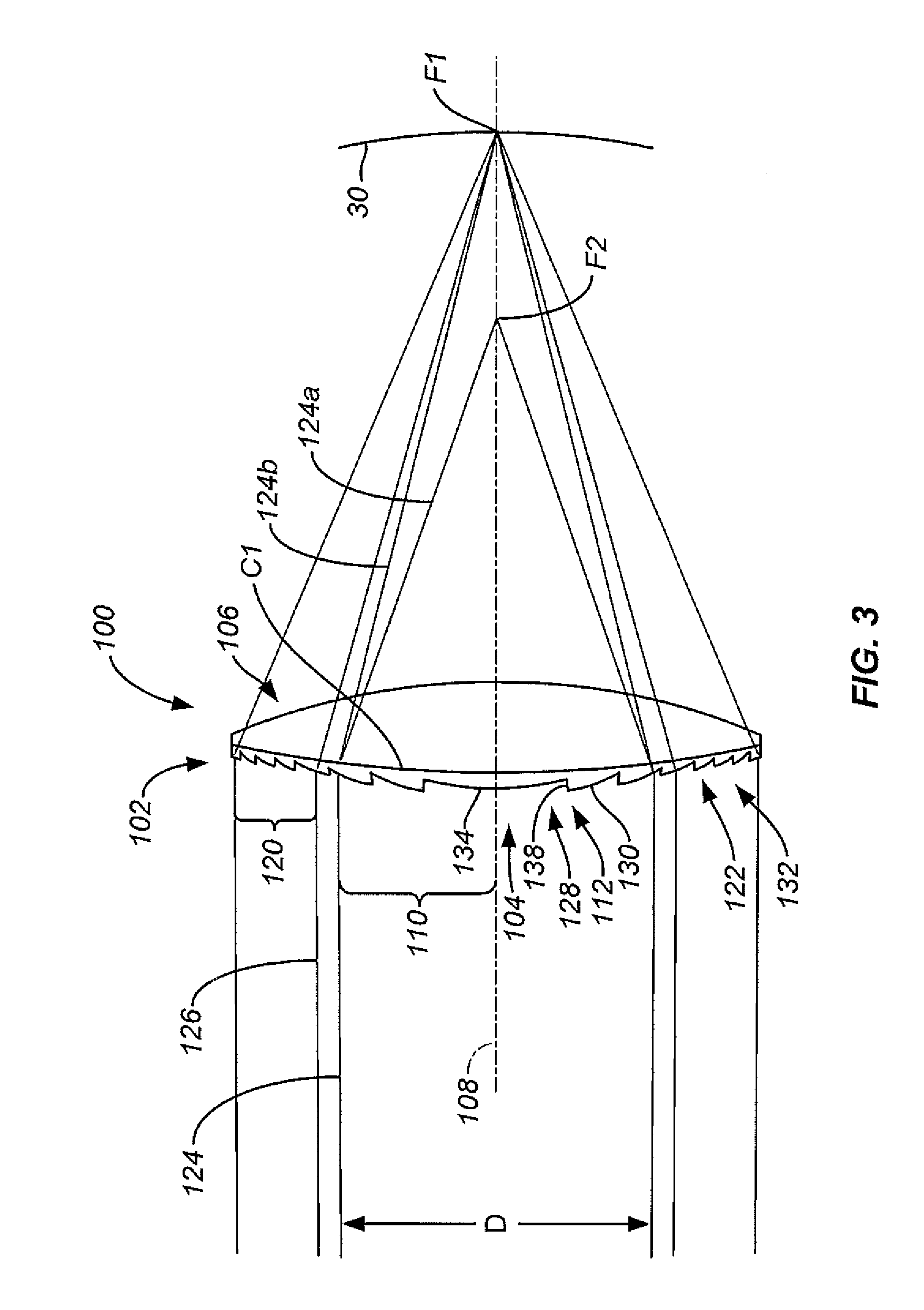
[0032]The present invention is directed to an ophthalmic lens such as, for example, spectacles, contact lenses, corneal inlays or onlays, or intraocul...


PUM


Abstract

An ophthalmic lens, such as an intraocular lens (IOL), a phakic IOL or a corneal implant, and a system and method relating to same, having coupled thereto one or more rotationally asymmetric and / or non-continuous diffractive zones, such as for providing improved multifocal vision correction.

Description

CROSS-REFERENCES TO RELATED APPLICATIONS[0001]This application claims priority under 35 U.S.C §119(e) to provisional application No. 61 / 288,255 filed on Dec. 18, 2009, the entire contents of which are incorporated herein by reference. This application is related to the following applications which were filed concurrently herewith: Single Microstructure Lens, Systems And Methods, U.S. patent application Ser. No. ______; Limited Echelette Lens, Systems And Methods, U.S. patent application Ser. No. ______; and Ophthalmic Lens, Systems And Methods Having At Least One Rotationally Asymmetric Diffractive Structure, U.S. patent application Ser. No. ______. The entire contents of these three applications are also incorporated herein by reference. This application is also related to the following U.S. Patent Application No. 61 / 047,699 and Ser. Nos. 12 / 109,251, both filed on Apr. 24, 2008; 12 / 429,155 filed on Apr. 23, 2009; 12 / 372,573 filed on Feb. 17, 2009; 12 / 197,249 filed on Aug. 23, 2008;...

Claims


Application Information

Patent Timeline
29 Dec 2011
Publication
US20110317124A1
IPC
G02C7/02
CPC
A61F2/1618; A61F2/1654; G02C7/041; G02C7/049; G02C7/06; G02C7/027; A61F2/1613; G02C2202/20
Inventors
WEEBER, HENDRIK A.; CATLIN, SCOTT J.