
Method and Device for Position Detection

a position detection and position detection technology, applied in the direction of resistance/reactance/impedence, instruments, force measurement, etc., can solve the problems of insufficient accuracy, insufficient establishment and storage of the comparison value for each intersecting point, and insufficient accuracy

Active Publication Date: 2012-01-12
EGALAX EMPIA TECH INC
View PDF1 Cites 5 Cited by
  • Summary
  • Abstract
  • Description
  • Claims
  • Application Information

AI Technical Summary

Benefits of technology

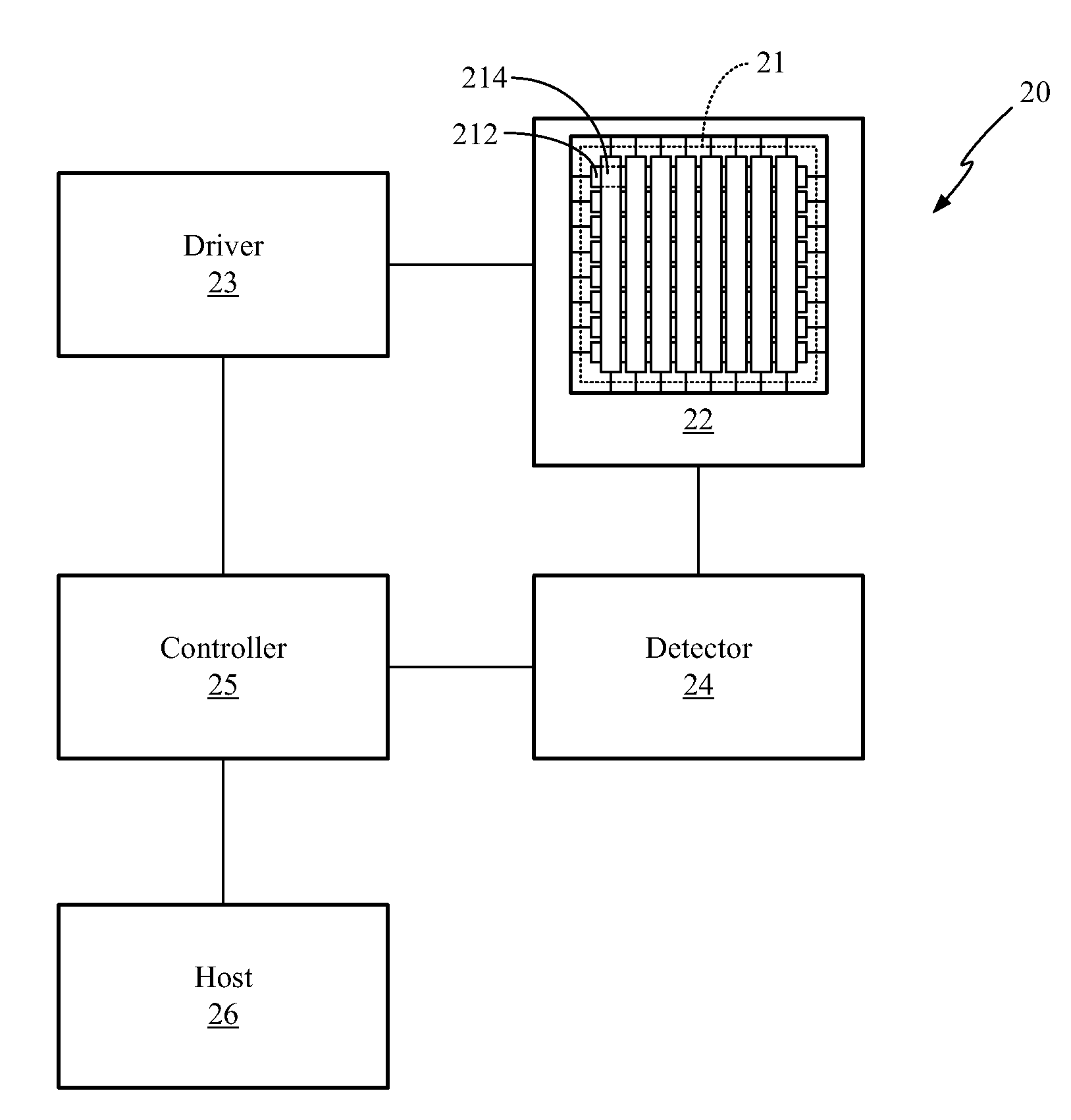
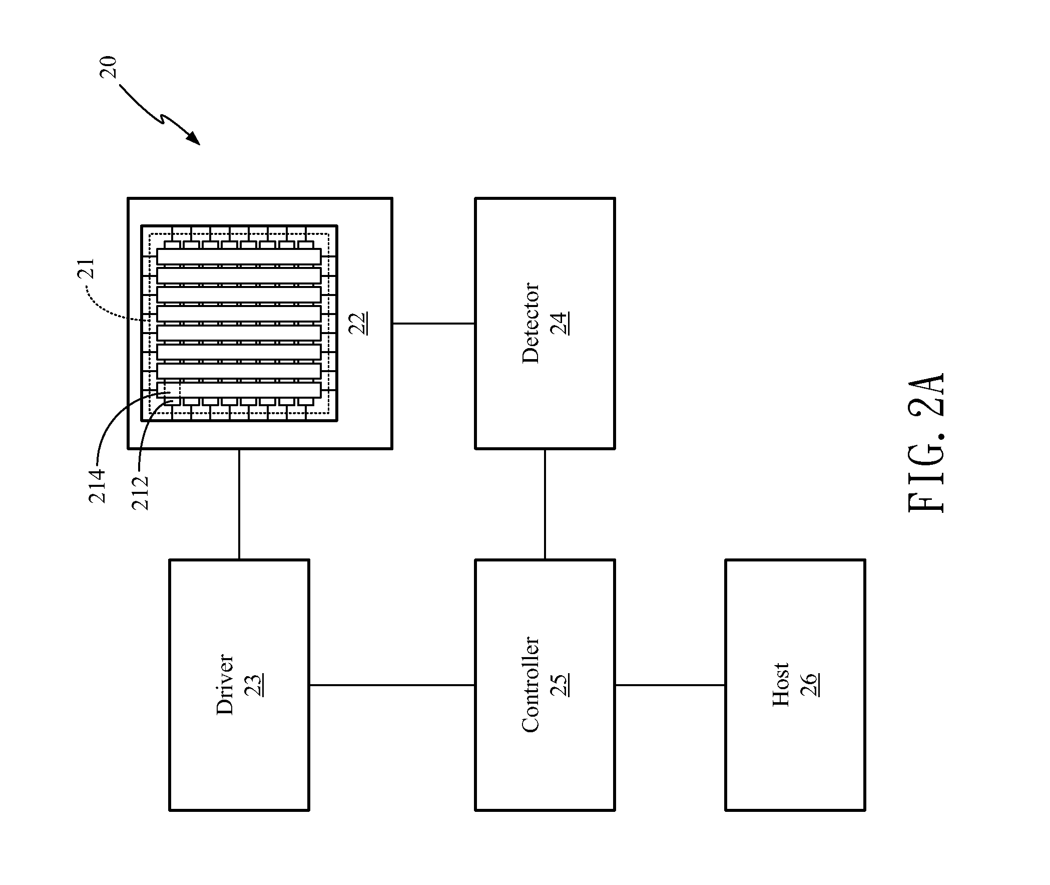
[0011]Through the detection of depressed conductive stripes, the search for depressed intersecting regions can be narrowed. Through the detection of depressed intersecting regions, the search for contact points can be narrowed. Thus, the method and device for position detection of the present invention can speed up the detection of all contact points. The position of each contact point can be expressed by two-dimensional coordinates.
[0032]A seventh objective of the present invention is to provide a method and device for omitting palms using multiple position detection. The present invention defines an omitted area on a second type of contact / depression detection using a first type of contact / depression detection, wherein the omitted area may include a plurality of independent omitted areas. The first type of detection is used to define depressions made by a palm or depressions with large areas, i.e. areas to be omitted, so when using the second type of position detection, depressions or contacts in the omitted area can be ignored. The first type of detection is a more coarse way of detecting multiple depressions or contacts, and the second type of detection more accurately detects depressions or contacts outside the omitted area, therefore having the advantages of fast detection and high accuracy at the same time.

Problems solved by technology

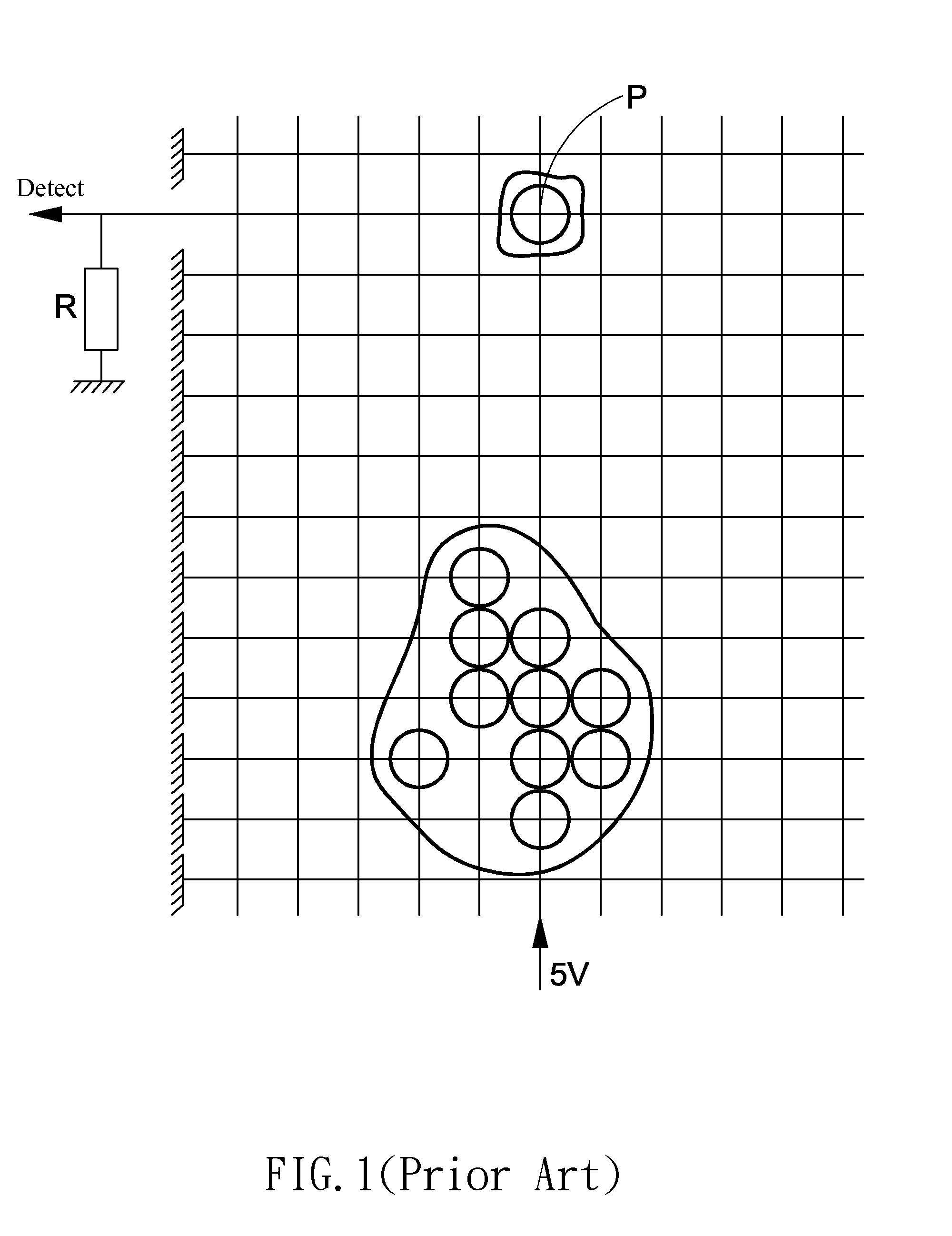
However, this approach may still be not accurate enough when the number of depressed intersecting points is large.
The establishment and storage for the comparison values for each intersecting point are clearly costly and not accurate enough.

Method used


Image

  • Method and Device for Position Detection
  • Method and Device for Position Detection
  • Method and Device for Position Detection

Examples


Embodiment Construction

[0078]The present disclosure can be described by the embodiments given below. It is understood, however, that the embodiments below are not necessarily limitations to the present disclosure, but are used to a typical implementation of the invention.

[0079]Having summarized various aspects of the present invention, reference will now be made in detail to the description of the invention as illustrated in the drawings. While the invention will be described in connection with these drawings, there is no intent to limit it to the embodiment or embodiments disclosed therein. On the contrary the intent is to cover all alternatives, modifications and equivalents included within the spirit and scope of the invention as defined by the appended claims.

[0080]It is noted that the drawings presents herein have been provided to illustrate certain features and aspects of embodiments of the invention. It will be appreciated from the description provided herein that a variety of alternative embodimen...


PUM


Abstract

A device comprises a plurality of strips intersecting each other to form a plurality of intersecting regions. A pair of strips intersecting on an intersecting region contact to each other on a contact point to form a depressed intersecting region. The erroneously determined intersecting regions can be detected by comparing the contact points with the corresponding intersecting regions so as to provide the only correct contact points.

Description

CROSS REFERENCE TO RELATED APPLICATIONS[0001]This application is a continuation of U.S. patent application Ser. No. 12 / 761,930, filed Apr. 16, 2010, which claims the benefit of U.S. Provisional Application No. 61 / 301,661, filed on Feb. 5, 2010, and Provisional Application No. 61 / 245,063, filed on Sep. 23, 2009, which are herein incorporated by reference for all intents and purposes.BACKGROUND OF THE INVENTION[0002]1. Field of the Invention[0003]The present invention relates to a method and device for position detection, and more particularly, to a method and device for depressed position detection.[0004]2. Description of the Prior Art[0005]In U.S. Patent Application Publication No. 2007 / 0198926, Jouget et al. discloses a device for detecting position, which includes an upper electrode layer and a lower electrode layer. The upper and lower electrode layers include a plurality of conductive stripes arranged in parallel in different directions. The upper and lower electrode layers are ...

Claims


Application Information

Patent Timeline
Patent Type & Authority Applications(United States)
IPC IPC(8): G01R27/28
CPCG06F3/045G01L1/205G06F2203/04104
Inventor YEH, SHANG-TAICHEN, JIA-MINGHO, SHUN-LUNG
Owner EGALAX EMPIA TECH INC
Learn More