Detector configuration apparatus, method, and program

a configuration apparatus and a technology of a detector, applied in the field of detector configuration apparatus, method and program, can solve the problems of not always performing efficient detection and no method known, and achieve the effect of higher resolution

Inactive Publication Date: 2012-01-19
FUJIFILM CORP
View PDF4 Cites 0 Cited by
  • Summary
  • Abstract
  • Description
  • Claims
  • Application Information

AI Technical Summary

Benefits of technology

[0021]The detection stage determination unit may be a unit that determines any of the plurality of modality types having a representative value of variation determined by the representative value determination unit greater than or equal to a threshold value Th (1) set to a first stage when the plurality of detection stages is arranged in ascending order of resolution to be detected in the first detection stage onward and any of the plurality of modality types having a representative value of variation determined by the representative value determination unit greater than or equal to a threshold value Th(i+1)(i is an integer in the range from 1 to the number of stages minus 1) set to (i+1)th stage and smaller than a threshold value Th(i) set to ith stage to be detected in the (i+1)th stage onward.
[0022]The detection stage determination unit may be a unit that compares a representative value of variation of teacher data corresponding to a modality type determined to be detected in a certain detection stage with a predetermined threshold value and excludes the modality type from a detection target list for a detection stage having higher resolution than that of the certain detection stage when the representative value of variation of teacher data is greater than or equal to the predetermined threshold value.

Problems solved by technology

Consequently, detectors have different configurations depending on the designers and efficient detection is not always performed.
Heretofore, no method has been known for objectively determining in which stage of a plurality of stages, from coarse detection to fine detection, a plurality of types of states or attributes is to be detected.

Method used


Image

  • Detector configuration apparatus, method, and program
  • Detector configuration apparatus, method, and program
  • Detector configuration apparatus, method, and program

Examples


Embodiment Construction

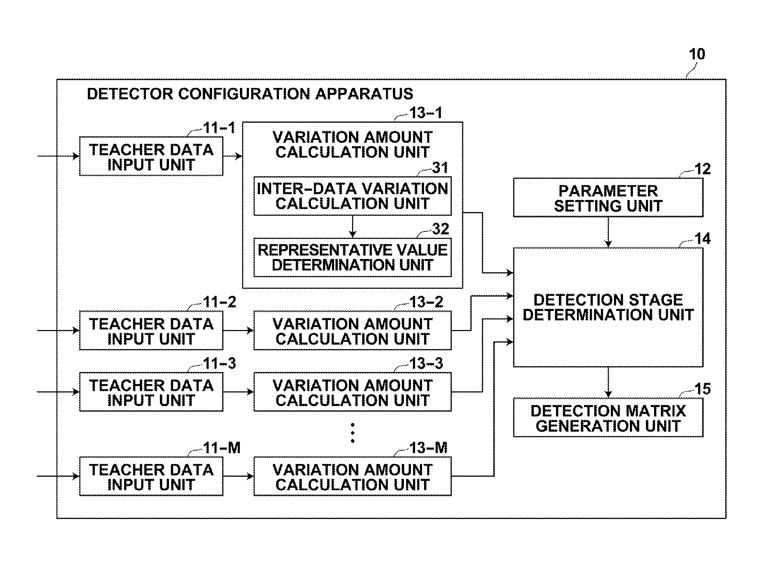
[0041]Hereinafter, embodiments of the present invention will be described in detail with reference to the accompanying drawings. FIG. 1 illustrates a detector configuration apparatus according to a first embodiment of the present invention. Detector configuration apparatus 10 includes teacher data input unit 11, parameter setting unit 12, variation amount calculation unit 13, detection stage determination unit 14, and detection matrix generation unit 15. Detector configuration apparatus 10 is an apparatus for determining the configuration of a detector that detects a detection target state or attribute of an object (also, called as “detection target modality”) included in input data. The function of each unit may be realized by causing a computer to perform processing according to a predetermined program. Alternatively, the function of each unit may be realized by an IC (Integrated Circuit).

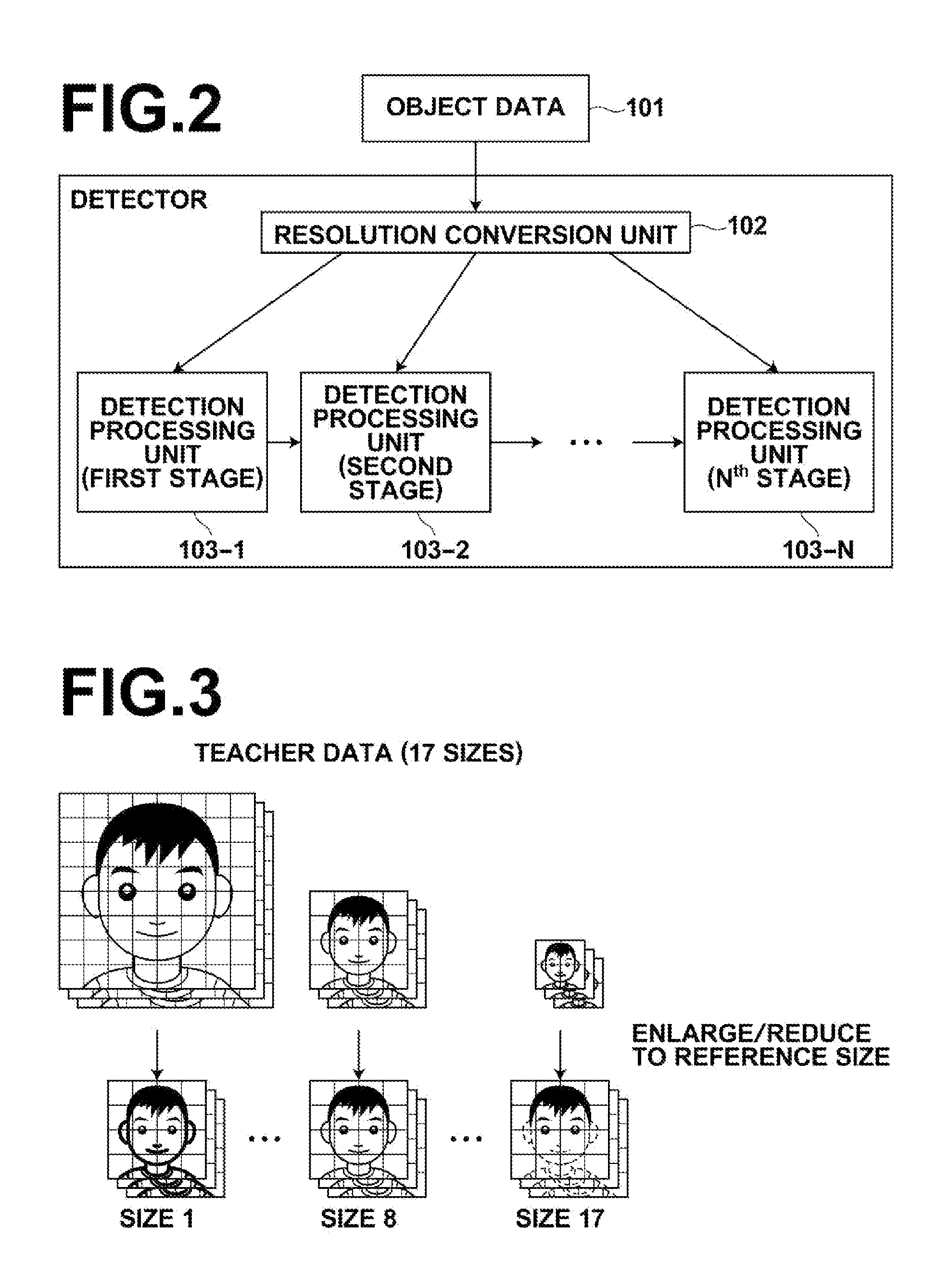
[0042]FIG. 2 illustrates a detector configured by detector configuration apparatus 10. Detect...


PUM


Abstract

A detector configuration apparatus for configuring a detector that performs detection through a plurality of detection stages with different resolutions capable of objectively determining a detection target modality type to be detected in each stage. The detector is configured to detect to which of a plurality of attribute values an attribute of an object included in input data corresponds with respect to each of a plurality of modality types. A variation amount calculation unit obtains, based on a plurality of teacher data corresponding to each modality type used for training the detector, a representative value of variation between a plurality of teacher data with respect to each modality type, and a detection stage determination unit determines in which stage of the plurality of detection stages each modality type is to be detected based on the representative value of variation between the teacher data.

Description

BACKGROUND OF THE INVENTION[0001]1. Field of the Invention[0002]The present invention relates generally to a detector configuration apparatus, method, and program and more specifically to a detector configuration apparatus and method for configuring a detector for detecting a state or attribute of an object based on teacher data used for training the detector. The invention also relates to a computer readable recording medium on which is recorded a program for causing a computer to perform the method.[0003]2. Description of the Related Art[0004]Object detection techniques for detecting an object, such as a human face, from an input image are known. In the field of object detection, techniques for detecting an object using a plurality of images having different resolutions (image sizes) are also known. Japanese Unexamined Patent Publication No. 2007-265390 is a document that describes object detection using images in a plurality of stages (paragraphs [0022], [0023], and [0119] to [01...

Claims


Application Information

Patent Timeline
Patent Type & Authority Applications(United States)
IPC IPC(8): G06F15/18G06N5/02
CPCG06K9/00241G06V40/164
Inventor KAMEYAMA, HIROKAZUYAMAGUCHI, KOUJI
Owner FUJIFILM CORP
Why Eureka
Try Eureka