
Posterior segment drug delivery

a technology for the posterior segment of the eye and drug delivery, which is applied in the direction of eye treatment, peptide/protein ingredients, instruments, etc., can solve the problems of less than ideal delivery of drugs, damage to the retina, and eye diseases that affect vision, so as to reduce the frequency of negative side effects

Active Publication Date: 2012-02-02
FORSIGHT VISION5 INC
View PDF3 Cites 47 Cited by
  • Summary
  • Abstract
  • Description
  • Claims
  • Application Information

AI Technical Summary

Benefits of technology

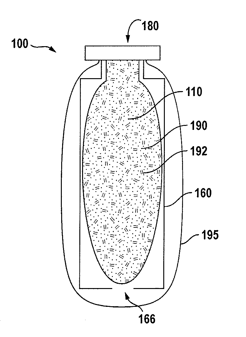
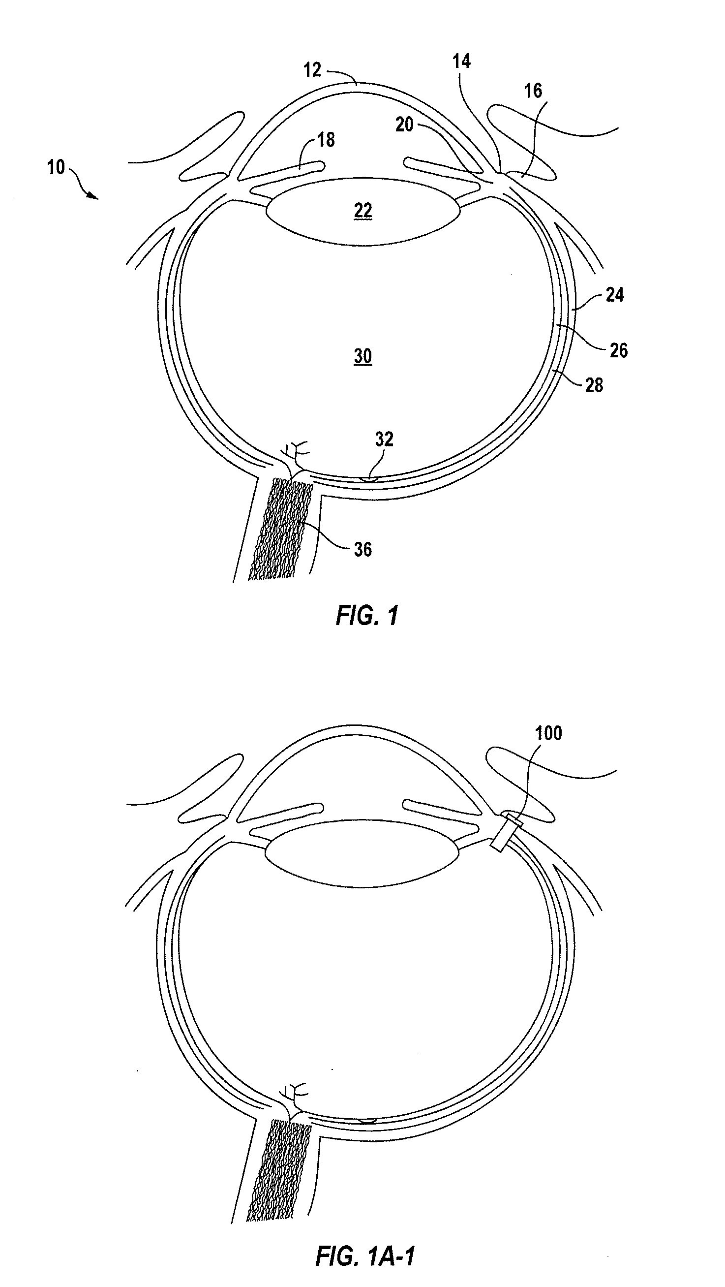
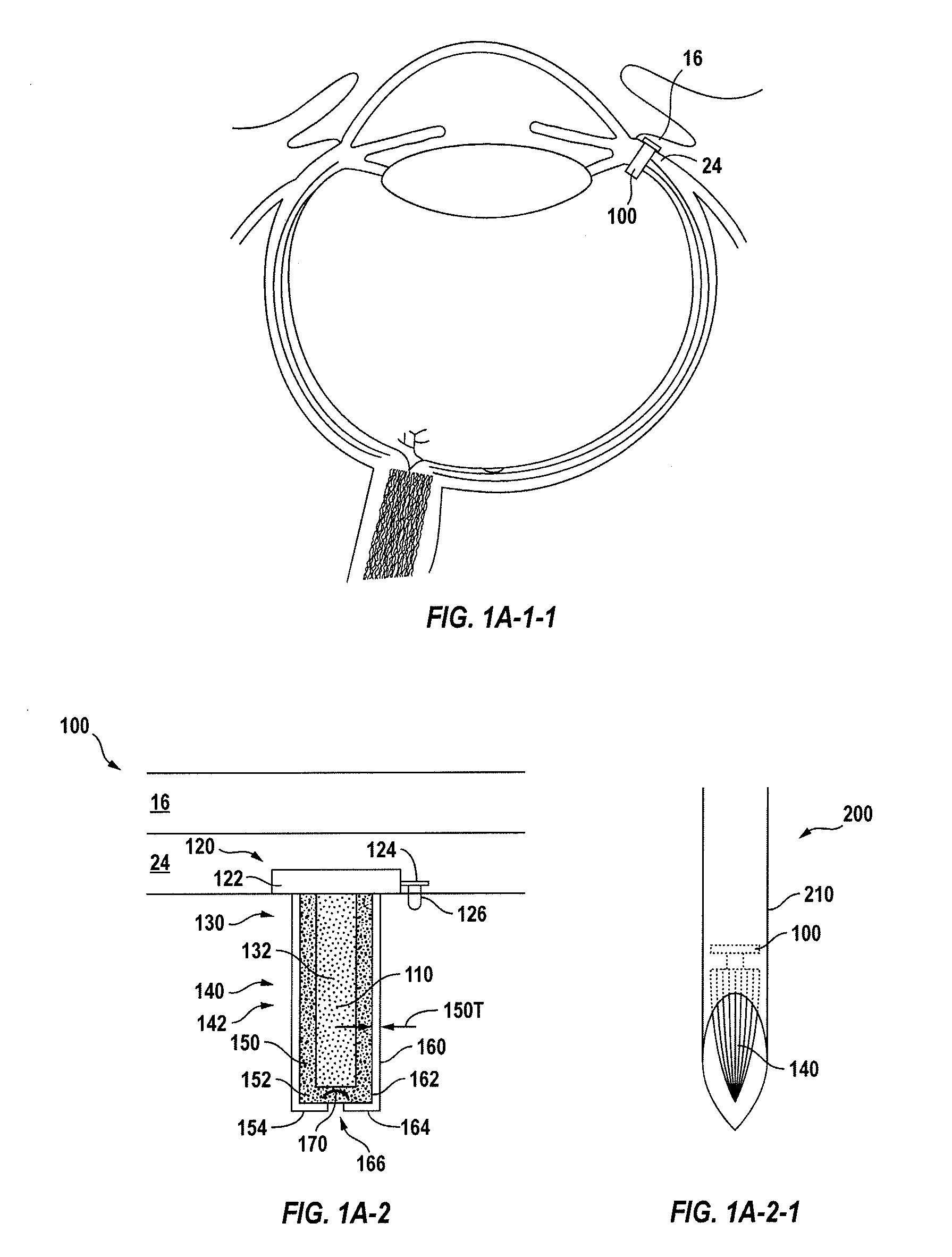
[0012]Embodiments of the present invention provide therapeutic devices that deliver therapeutic amounts of a therapeutic agent for an extended time to the posterior segment of the eye, for example an extended time of at least about 1 month. The therapeutic device may reduce the frequency of negative side effects associated with direct intraocular injection such as pain, retinal detachment, hemorrhaging and infection because injections can be made less frequently and can be made into the reservoir of the device rather than into the eye. The therapeutic device can be configured to replace the therapeutic agent when the device is implanted at least partially within the eye of the patient. The therapeutic device may be implanted in the eye so as to extend through the sclera of the eye, and the therapeutic device may comprise a container and a port or penetrable barrier configured to receive a quantity of therapeutic agent. The therapeutic agent can be placed in the container in many ways, for example by placing a solid insert through the port to the inside of the container or by injecting a formulation of the therapeutic agent through the penetrable barrier into the container. The therapeutic device may comprise a binding agent that reversibly or releasably couples to the therapeutic agent such that the therapeutic agent is released from the device for the extended time.
[0013]In many embodiments, the therapeutic device is configured to provide continuous release of therapeutic quantities of at least one therapeutic agent for an extended time of at least 3 months, for example 6 months, such that the frequency of injections into the therapeutic device and risk of infection can be substantially decreased. In additional embodiments, the therapeutic device is configured to provide continuous release of therapeutic quantities of at least one therapeutic agent for an extended time of at least 12 months, or at least 2 years or at least 3 years.
[0014]The therapeutic device can be configured in many ways to release the therapeutic agent for the extended time and may comprise at least one of an opening, an elongate structure, a porous structure, or a porous surface sized to release the therapeutic agent for the extended time. For example, the therapeutic device may comprise the porous structure to release the therapeutic agent through the porous structure for the extended period. The porous structure may comprise a sintered material having many channels, for example interconnecting channels, extending around many particles adhered to each other. The porous structure may comprise a first side comprising a first plurality of openings coupled to the reservoir and a second side comprising a second plurality of openings to couple to the vitreous humor. The interconnecting channels may extend between each of the first plurality of openings of the first side and each of the second plurality of openings of the second side so as to maintain release of the therapeutic agent through the porous structure, for example when at least some the openings are blocked. The porous structure can be rigid and maintain release of the therapeutic agent through the interconnecting channels when tissue or cells cover at least a portion of the openings, for example when the porous structure is implanted for an extended time and the drug reservoir refilled.

Problems solved by technology

Unfortunately, diseases can affect vision.
In some instances the disease affecting vision can cause damage to the retina, even blindness in at least some instances.
Although therapeutic drugs are known that can be provided to minimize degradation of the retina, in at least some instances the delivery of these drugs can be less than ideal.
Unfortunately, in at least some instances injection of drugs can be painful for the patient, involve at least some risk of infection and hemorrhage and retinal detachment, and can be time consuming for the physician and patient.
Although some implant devices have been proposed, many of the known devices are deficient in at least some respects in at least some instances.
At least some of the known implanted devices do not provide sustained release of a therapeutic drug for an extended period.
For example, at least some of the known implanted devices may rely on polymer membranes or polymer matrices to control the rate of drug release, and many of the known membranes and matrices may be incompatible with at least some therapeutic agents such as ionic drugs and large molecular weight protein drugs in at least some instances.
At least some of the known semi-permeable polymer membranes may have permeability that is less than ideal for the extended release of large molecular weight proteins such as antibodies or antibody fragments.
At least some of the known implantable devices can result in patient side effects in at least some instances when a sufficient amount of drug is delivered to treat a condition of the eye.
For example, at least some of the commercially available small molecule drug delivery devices may result in patient side effects such as cataracts, elevated intraocular pressure, dizziness or blurred vision in at least some instances.
Although corticosteroids and analogues thereof may be delivered with an implanted device to treat inflammation, the drug delivery profile can be less than ideal such that the patient may develop a cataract in at least some instances.
Although at least some of the proposed implanted devices may permit an injection into the device, one potential problem is that an injection into an implanted device can cause at least some risk of infection for the patient in at least some instances.
Also, in at least some instances the drug release rate of an implanted device can change over time, such that the release rate of the drug can be less than ideal after injection in at least some instance.
Also, work in relation to embodiments of the present invention suggests that at least some of the proposed implanted devices do not provide adequate protection from the patient's immune system, such as from macrophages and antibodies, thereby limiting the therapeutic effect in at least some instances.

Method used


Image

  • Posterior segment drug delivery
  • Posterior segment drug delivery
  • Posterior segment drug delivery

Examples


example 1

[0582]

TABLE 1CRelease of Fluorescein through Exit PortNeedleReleaseReservoirNeedleIDAreaRateNumberGauge(mm)(mm{circumflex over ( )}2)(ug / day)1180.8380.55210.82180.8380.5529.43230.3180.0791.04230.3180.0791.25300.140.0150.66300.140.0150.6

[0583]The initial release rate (averaged over 0.5-4 days) is proportional to the area of the exit port opening.

[0584]The cumulative amount released into the vials is shown in FIG. 9. The amount released in a week ranged from 2 to 20%. An average delivery rate was determined from the slope for data collected between 0.5 and 4.5 days and is reported in Table 1C. FIG. 10 shows that the initial release rate is approximately proportional to the area of the exit port opening.

example 2

[0585]FIG. 11 shows reservoirs with a porous membrane fabricated by cutting off the Luer-Lok tip on 1 mL syringes. The end of the syringe was smoothed and beveled. A nylon membrane with 0.2 μm pore size was placed over the end of the syringe and secured with a piece of silicone tubing. The inner diameter of the syringe was 4.54 mm, yielding an exposed membrane area of 16 mm2 The piston was removed so that approximately 100 mL of 300 mg / mL bovine serum albumin (BSA, Sigma A7906-100G) in PBS could be added. The piston was replaced and moved to remove the air and to push a small amount of the liquid through the membrane. The outside of the membrane and syringe was rinsed by submerging briefly in water. The reservoirs were then placed into 15 mL vials containing 5 mL PBS. The tops of the vials were sealed with parafilm to avoid evaporation. At periodic intervals of 0.5-1 day, the reservoirs were moved to new vials containing PBS. Diffusion through the membrane was determined by measurin...

example 3

[0586]An experiment was performed to screen chromatographic media (Bio-Rad) for binding to Human IgG (Jackson ImmunoResearch, ChromPure). Columns were packed with the ten media listed below and were equilibrated in 20 mM acetate buffer pH 4.5.

TABLE 2Macro-Prep t-Butyl HIC SupportMacro-Prep DEAE SupportCHT Ceramic Hydroxyapatite Type I 40 umMacro-Prep CM SupportMacro-Prep Methyl HIC SupportMacro-Prep Ceramic Hydroxyapatite Type II 40 umUNOsphere S Cation Exchange SupportUNOsphere Q Strong Anion Exchange SupportMacro-Prep High S SupportMacro-Prep High Q Support

[0587]Then, 0.5 mL aliquots of 1 mg / mL antibody in 20 mM acetate buffer pH 4.5 were gravity-driven through the column and the collected solution was assessed qualitatively for color change using a BCA™ protein assay kit (Pierce). Of the media tested, Macro-Prep CM Support, Macro-Prep High S Support, and Macro-Prep Ceramic Hydroxyapatite Type II 40 um each successfully bound IgG. Subsequently, PBS was washed through the columns a...


PUM

PropertyMeasurementUnit
timeaaaaaaaaaa
timeaaaaaaaaaa
timeaaaaaaaaaa

Abstract

A therapeutic device to release a therapeutic agent comprises a porous structure coupled to a container comprising a reservoir. The reservoir comprises a volume sized to release therapeutic amounts of the therapeutic agent for an extended time when coupled to the porous structure and implanted in the patient. The porous structure may comprise a first side coupled to the reservoir and a second side to couple to the patient to release the therapeutic agent. A plurality of interconnecting channels can extend from the first side to the second side so as to connect a first a plurality of openings on the first side with a second plurality of openings on the second side.

Description

CROSS-REFERENCES TO RELATED APPLICATIONS[0001]The present application is a continuation of Ser. No. 12 / 696,678 filed 29 Jan. 2010 (attorney reference number 003750US), which application claims priority to U.S. Provisional Application Nos. US 61 / 148,375 filed Jan. 29, 2009, entitled, “POSTERIOR SEGMENT DRUG DELIVERY” (attorney reference number 003700US); 61 / 174,887 filed May 1, 2009, entitled “POSTERIOR SEGMENT DRUG DELIVERY” (attorney reference number 003710US); 61 / 261,717 filed Nov. 16, 2009, entitled “POSTERIOR SEGMENT DRUG DELIVERY” (attorney reference number 003720US); and 61 / 284,832 filed on Dec. 24, 2009, entitled “POSTERIOR SEGMENT DRUG DELIVERY” (attorney reference number 003730US); and 61 / 299,282 filed Jan. 28, 2010, entitled “POSTERIOR SEGMENT DRUG DELIVERY” (attorney reference number 003740US); the full disclosures of which are incorporated herein by reference.STATEMENT AS TO RIGHTS TO INVENTIONS MADE UNDER FEDERALLY SPONSORED RESEARCH AND DEVELOPMENT[0002]NOT APPLICABLEB...

Claims


Application Information

Patent Timeline
Patent Type & Authority Applications(United States)
IPC IPC(8): A61F9/00
CPCA61F9/0017A61K9/0048A61K9/0051Y10T29/49826A61K31/573G01N33/558A61K31/57A61K31/58A61K38/385A61P27/02A61K47/32A61K47/34A61K47/38A61K2039/505C07K16/22C07K2317/24C07K2317/55
Inventor JUAN, JR., EUGENE DEALSTER, YAIRFARINAS, KATHLEEN COGANGIFFORD, III, HANSON S.MACFARLANE, K. ANGELAREICH, CARY J.BARRETTCAMPBELL, RANDOLPH E.SUTTON, DOUGLAS
Owner FORSIGHT VISION5 INC
Learn More