Cutting tool with unequal flute spacing

a cutting tool and flute spacing technology, applied in the field of cutting tools, can solve the problems of irregular surface structure of the boring wall, deterioration of the quality of the boring over the length of the drilling process, and vibrations of the drill that cause the “chatter” recur periodically

Active Publication Date: 2012-02-09
KENNAMETAL INC
View PDF15 Cites 25 Cited by
  • Summary
  • Abstract
  • Description
  • Claims
  • Application Information

AI Technical Summary

Benefits of technology

[0008]These and other aspects of the present invention will be more fully understood following a review of this specification and drawings.

Problems solved by technology

The '603 patent and the '268 patent publication describe the problem known in the technical literature as “chatter”, a problem that is experienced with a drill during the drilling process when the irregular rotational action of the drill during the drilling process results in an irregular surface structure of the boring wall.
This symmetrical distribution has the further disadvantage that the vibrations of the drill that cause the “chatter” recur periodically during the drilling process.
The result is that the irregularities in the side walls of the hole which is being bored, which irregularities are also called ““chatter marks”” increase, resulting in a deterioration in the quality of the boring over the length of the drilling process.

Method used


Image

  • Cutting tool with unequal flute spacing
  • Cutting tool with unequal flute spacing
  • Cutting tool with unequal flute spacing

Examples


Embodiment Construction

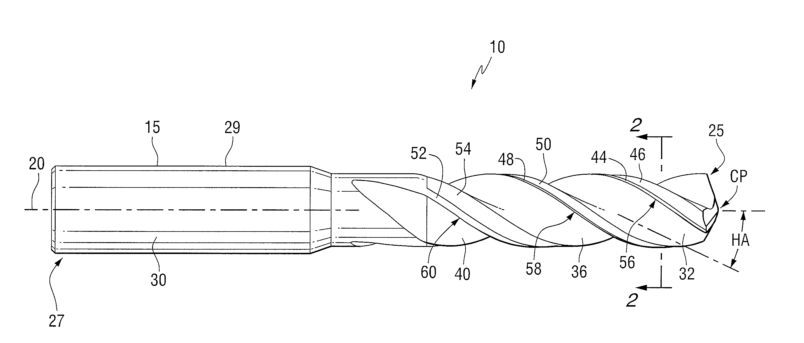
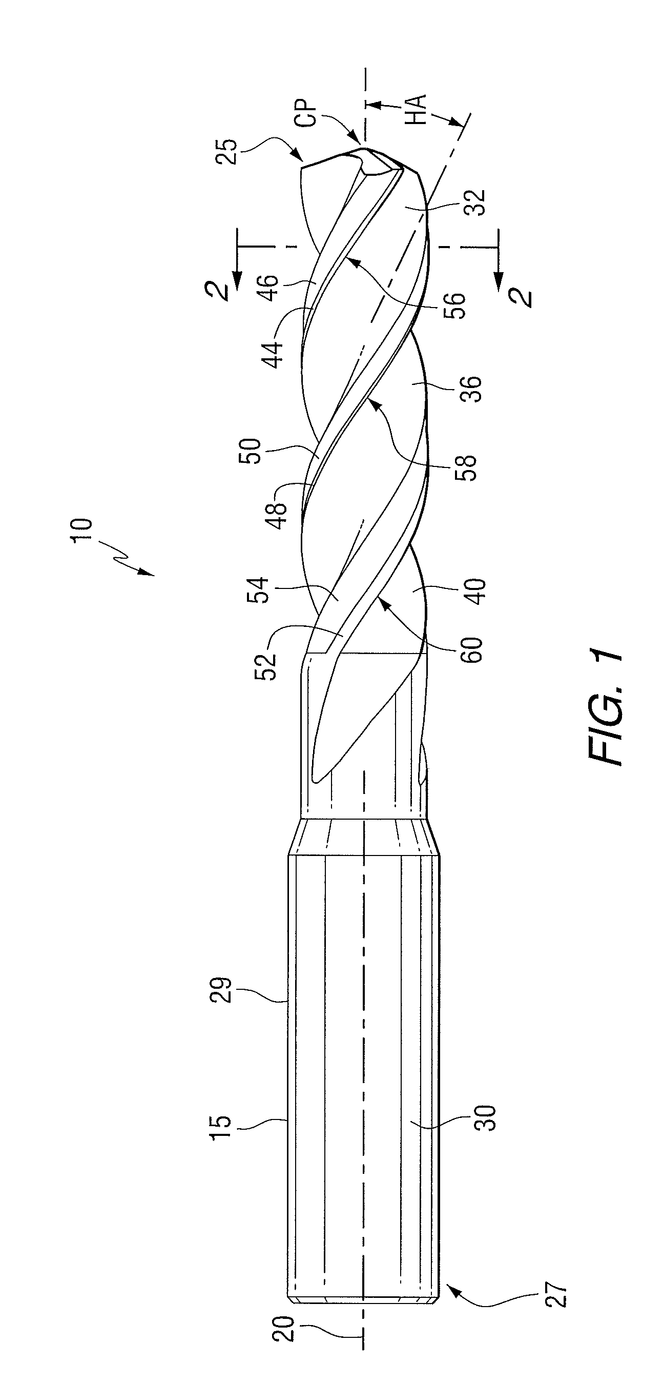
[0012]In one aspect of the invention, the invention is directed to a cutting tool having a helical flute. For purposes of explanation, a twist drill will be described herein with the understanding that the invention is applicable to other cutting tools having helical flutes, such as, for example, taps and reamers.

[0013]Referring to FIGS. 1 and 2, there is shown a cutting tool 10 which, for purposes of description herein, will be referred to as a twist drill, having a shaft 15 with a longitudinal axis 20. The shaft 15 has a forward end 25 capable of contacting and cutting a work piece (not shown). At a rearward end 27 of the shaft 15 is a shank 29, which may be generally cylindrical, or may have a non-cylindrical shape to fit within a chuck (not shown). While the shank 29 is illustrated as cylindrical, it should be appreciated that the shank 29 may have other shapes such as, for example, square, hexagonal, conical, or any other suitable non-cylindrical shape for gripping within a chu...


PUM

PropertyMeasurementUnit
angleaaaaaaaaaa
angleaaaaaaaaaa
angleaaaaaaaaaa

Abstract

A cutting tool having a shaft with a longitudinal axis, wherein the cutting tool includes a first flute extending about the longitudinal shaft along a helix angle and a first cutting edge adjacent the first flute. The cutting tool also includes a second flute extending about the longitudinal shaft along a helix angle and a second cutting edge adjacent a second flute. The cutting tool further includes a third flute extending about the longitudinal shaft along a helix angle and a third cutting edge adjacent the third flute. The first cutting edge, the second cutting edge, and the third cutting edge are unequally angularly spaced from each other.

Description

FIELD OF THE INVENTION[0001]The present invention relates to a cutting tool and, more particularly, relates to a cutting tool, such as a drill, with unequal flute spacing.BACKGROUND INFORMATION[0002]A cutting tool, such as a drill or twist drill, is generally comprised of a cylindrical shaft having at least one flute and land, which follow a helical angle to a forward cutting edge at the forward end of the shaft. The land has associated with it a margin and a clearance portion behind the margin. A side cutting edge is defined by the intersection of the flute with the margin of the land.[0003]An example of a drill of this type is shown, for example, in U.S. Pat. No. 4,913,603 and U.S. Patent Application Publication No. 2008 / 0199268 A1. The '603 patent and the '268 patent publication describe the problem known in the technical literature as “chatter”, a problem that is experienced with a drill during the drilling process when the irregular rotational action of the drill during the dri...

Claims


Application Information

Patent Timeline
Patent Type & Authority Applications(United States)
IPC IPC(8): B23B51/02
CPCB23B51/02B23B2251/202Y10T408/9097Y10T408/909Y10T408/9095B23B2251/282
Inventor KRIEG, TILO ERNSTGEY, CHRISTOPHGEORGE, STEPHEN MICHAEL
Owner KENNAMETAL INC
Why Eureka
Try Eureka