
Wall Movement Synchronization Slide-Out Room System and Method

a slide-out room and wall movement technology, applied in the direction of process and machine control, instruments, transportation items, etc., can solve the problems of leakage or draft between the slide-out room and the outside environment, system seals sometimes do not evenly compress at and cannot ensure the movement of the single side of the room with the other side of the room

Inactive Publication Date: 2012-02-09
LIPPERT COMPONENTS MFG INC
View PDF18 Cites 31 Cited by
  • Summary
  • Abstract
  • Description
  • Claims
  • Application Information

AI Technical Summary

Benefits of technology

[0007]In another aspect, the slide-out room system comprises a slide-out room movably connected to the vehicle. The slide-out room has a leading wall, a ceiling, a floor, and right and left side walls extending between the ceiling and the floor. The system further includes at least four room slides supported by the vehicle and operable to move the slide-out room relative to the vehicle. A first of the four room slides is disposed in a first quadrant defined by an upper half of the right side wall, a right half of the ceiling, and an upper right quarter of the leading wall, a second of the four room slides is disposed in a second quadrant defined by a left half of the ceiling, an upper half of the left side wall, and an upper left quarter of the leading

Problems solved by technology

In such a skewed position the slide-out room may not properly engage seals at interfaces between the slide-out room and the rest of the vehicle, which may ultimately cause leaks or drafts between the slide-out room and the outside environment.
Unfortunately, these systems could not ensure synchronized movement of the single side of the room with the other sides of the room (e.g., the ceiling and side walls) due to their distance from the actuators.
Similarly, these systems sometimes did not evenly compress seals at the other sides of the room.

Method used


Image

  • Wall Movement Synchronization Slide-Out Room System and Method
  • Wall Movement Synchronization Slide-Out Room System and Method
  • Wall Movement Synchronization Slide-Out Room System and Method

Examples


Embodiment Construction

[0026]A slide-out room system according to the present invention provides wall movement synchronization of several walls of the room, such as the ceiling, the floor, and the side walls. As such, the system ensures the slide-out room does not move to a skewed position relative to the vehicle. Moreover, the system provides sufficient engagement between the walls of the vehicle and seals on the slide-out room. These aspects of the invention are described in further detail in the following paragraphs, beginning with the structure of the slide-out room and concluding with methods for providing synchronized movement.

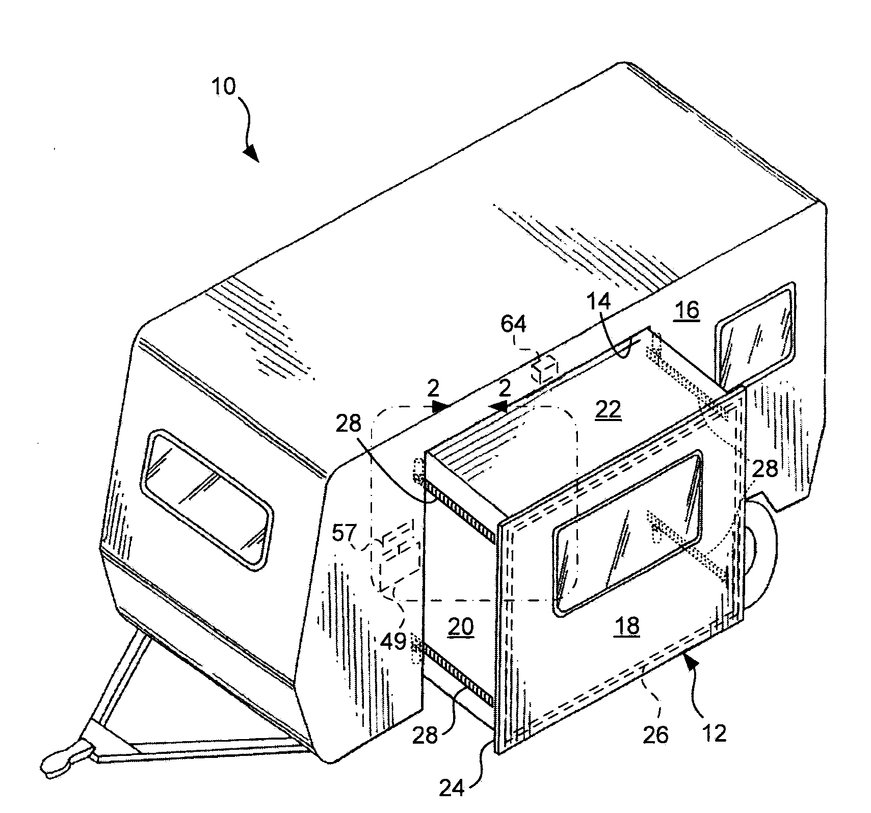
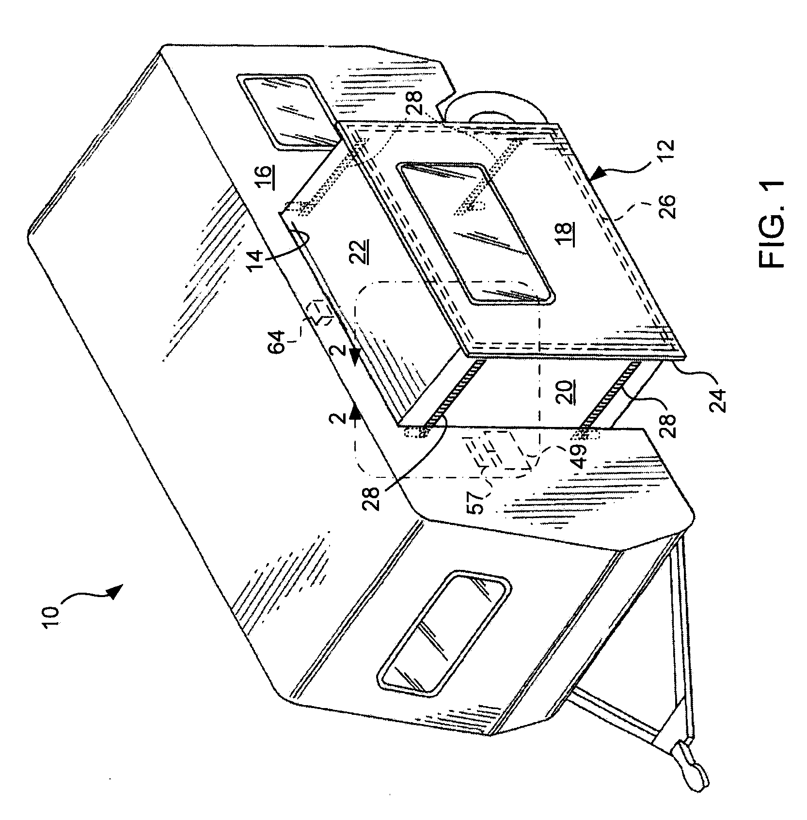
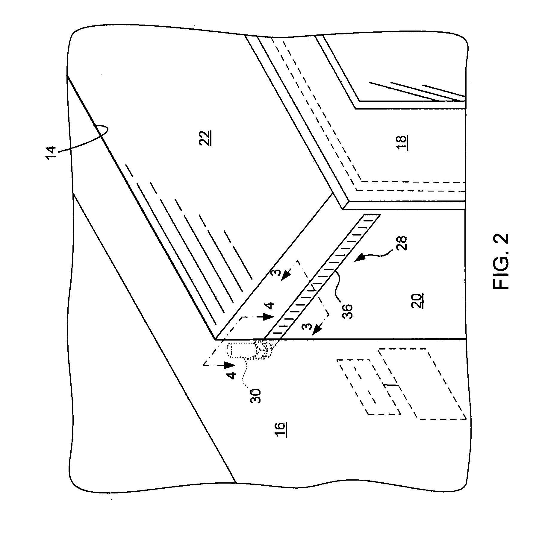
[0027]Referring first to FIGS. 1, 2, 5, and 6, a recreational vehicle 10 supports the slide-out room 12 in an opening 14 of a vehicle side wall 16. An interior of the slide-out room 12 is defined by a leading or outside wall 18, side walls 20, a ceiling 22, and a floor 23 (FIG. 5). The leading wall 18 includes a fascia 24, and the plane of the fascia 24 is parallel to the resp...


PUM


Abstract

A slide-out room system for a vehicle includes a slide-out room movably connected to the vehicle and at least four room slides supported by the vehicle and operable to move the slide-out room relative to the vehicle. A first of the four room slides is disposed in a first quadrant of the slide-out room, a second of the four room slides is disposed in a second quadrant of the slide-out room, a third of the four room slides is disposed in a third quadrant of the slide-out room, and a fourth of the four room slides is disposed in a fourth quadrant of the slide-out room. The system further includes a controller operatively connected to each of the four room slides for independently controlling the motion of the four room slides and synchronizing the motion of the four room slides to move the quadrants in concert with one another.

Description

CROSS-REFERENCE TO RELATED APPLICATIONS[0001]This application claims the benefit of U.S. Provisional Patent Application No. 61 / 371,557 filed Aug. 6, 2010, the disclosure of which is hereby incorporated by reference in its entirety.STATEMENT REGARDING FEDERALLY SPONSORED RESEARCH OR DEVELOPMENT[0002]Not applicable.FIELD OF THE INVENTION[0003]This invention generally relates to slide-out rooms of recreational vehicles, and more particularly, slide-out rooms having multiple room slides.BACKGROUND OF THE INVENTION[0004]Some recreational vehicles include a slide-out room to increase the size of the living quarters while also providing an appropriate size for highway travel. Some slide-out rooms extend from the side of a vehicle and are moved by one or more actuators, such as hydraulic cylinders, electric drive screws, or electric gear drives located on the vehicle. In the case of multiple actuators, a controller may be used to ensure synchronized movement of the actuators. Otherwise, the...

Claims


Application Information

Patent Timeline
IPC IPC(8): B60P3/34G06F17/00
CPCB60P3/34
Inventor KREIL, CRAIG J.
Owner LIPPERT COMPONENTS MFG INC
Learn More